|
End Shield Dismantle and Assemble (F17+/F17+
MTA)
Note: Transmission
remains installed.
Overview of End Shield
 Remove Remove
|
| 1. |
Remove gearbox cover (1)
Note: For F17+
transmission.
Remove gearshift module (2)
Note: For F17+ MTA
transmission.
|
| 2. |
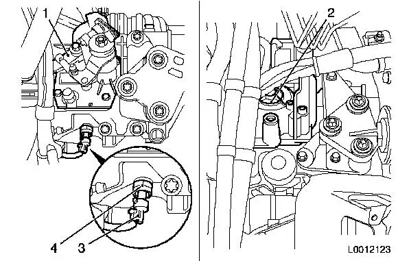
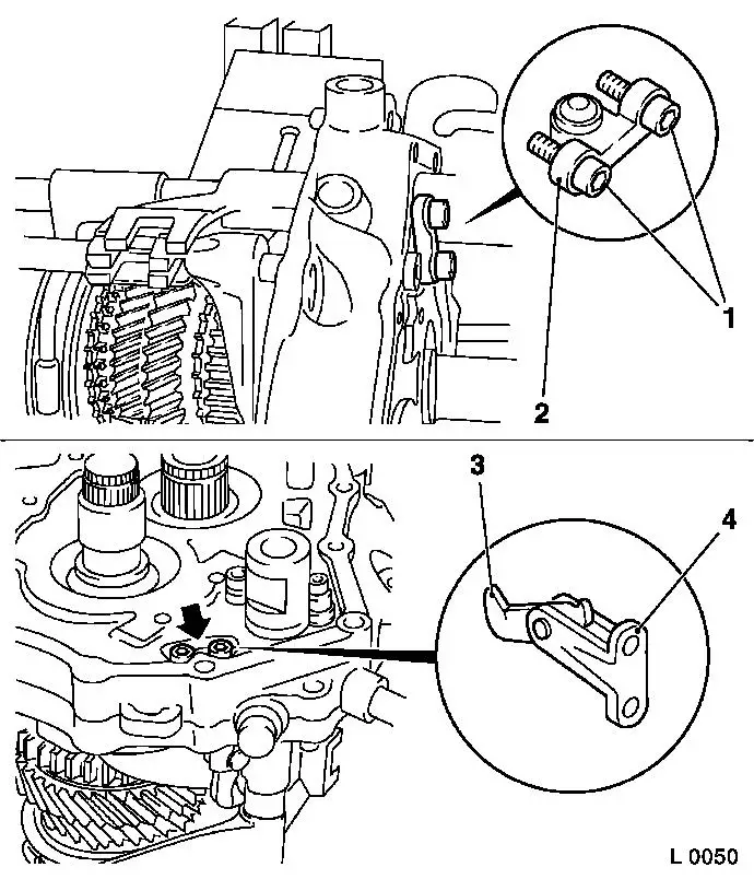
Remove reversing lamps switch (3).
| • |
Disconnect wiring harness plug, reversing lamp switch (4)
|
| • |
Unscrew reversing lamp switch
|
|
|
|
| 3. |
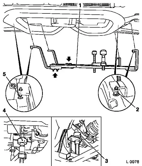
Attach KM-6001-B to front axle
body
| • |
Release 2x bolt (arrows) for adjustment rails on KM-6001-B (1)
|
| • |
Insert KM-6001-B as shown
Note: 2x journals (2)
and (5) must sit flush in the guide holes of the front axle
body.
|
| • |
Tighten 2x bolt for adjustment rails
|
| • |
Twist up front support bearing (4)
| – |
as far as the stop on the guide pin of the front engine damping
block
Note: The guide pins
must sit in the support bearings with no play.
|
|
| • |
Twist up rear support bearing (3)
| – |
as far as the stop on the guide pin of the rear engine damping
block bracket
Note: The guide pins
must sit in the support bearings with no play.
|
|
|
|
| 4. |
Remove front axle body
|
|
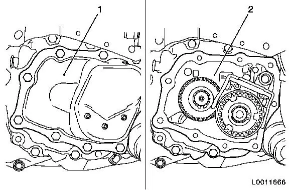
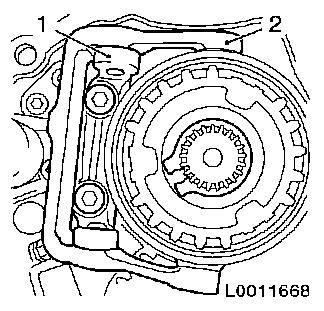
| 5. |
Remove end shield (1) cover 
|
|
|
| 7. |
Attach end shield to KM-552 (2)
|
| 8. |
Attach end shield to KM-113-2 (1)
using KM-552
|
|
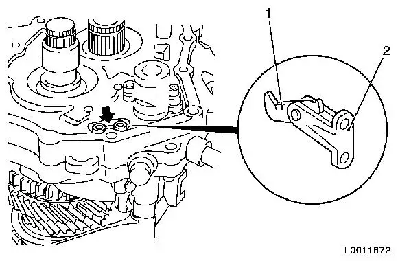
| 9. |
Remove bearing support (1) with rocker arm (2) from end
shield
Note:
Micro-encapsulated fastening bolts. If fastening bolts are stiff,
heat end shield with hot-air dryer to approximately 80 °C.
|
|
|
|
| 10. |
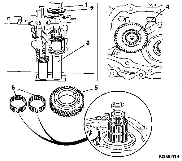
Remove 5th gear (driven)
| • |
Detach retaining ring from synchro body (1)
|
| • |
Pull gear wheel, 5th gear, and synchro body, 5th gear, away
from main shaft with KM-559-A (2)
|
| • |
Remove 2x needle bearing for gear wheel, 5th gear
|
|
|
|
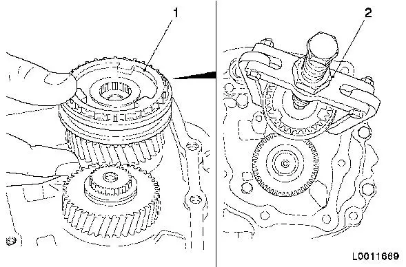
| 11. |
Detach gear wheel, 5th gear (driving)(2) from drive shaft
(3)
|
|
|
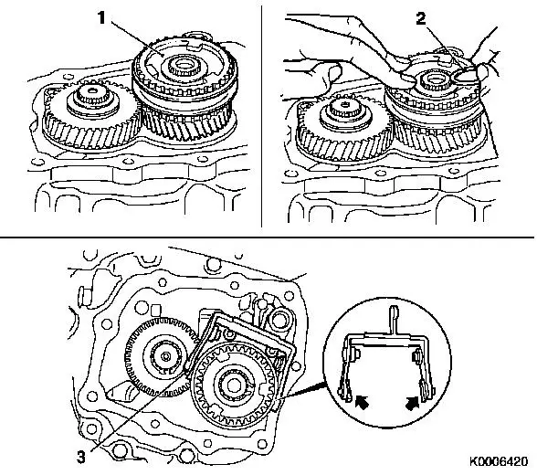
| 12. |
Detach gear wheel, 5th gear, (driving) from drive shaft with
KM-553-A (1)
Note: Ensure KM-553-A is correctly seated on the gear wheel,
5th gear (driving)
| • |
Place thrust piece (2) from KM-553-A
on drive shaft
|
|
|
|
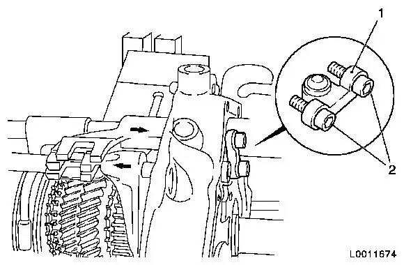
| 13. |
Detach bearing support (2) with pawl (1) from end shield
| • |
Remove 2x bolts (arrow)
Note:
Micro-encapsulated fastening bolts. If fastening bolts are stiff,
heat end shield with hot-air dryer to approximately 80 °C.
|
|
|
|
| 14. |
Remove locking plugs (arrows) from end shield
| • |
Remove locking plugs with KM-727 (2)
and KM-328-B (1)
|
|
|
|
| 15. |
Detach bridge (1) for end shield locking bolt
Note: The bridge will
push out if 3rd gear is then engaged
| • |
Unscrew 2x bolt (2)
Note:
Micro-encapsulated fastening bolts. If fastening bolts are stiff,
heat end shield with hot-air dryer to approximately 80 °C.
|
|
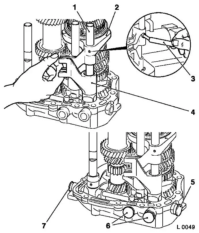
| 16. |
Engage 2nd gear and 5th gear
| • |
Engage 2x gear with shift carrier (arrows)
|
|
|
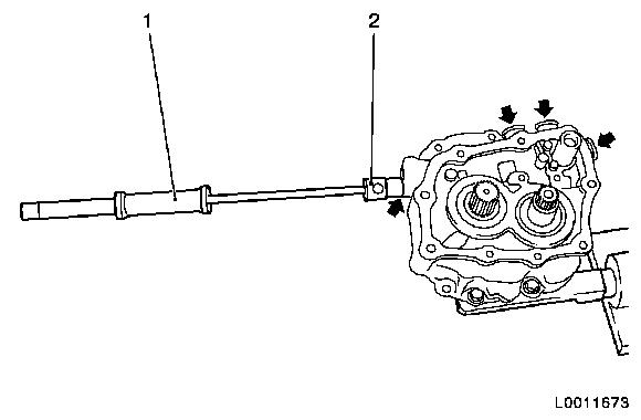
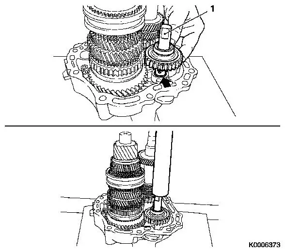
|
Important: Relieve pressure on
gearshift rod guides – for this, support gearshift rods above
with wood (1)
|
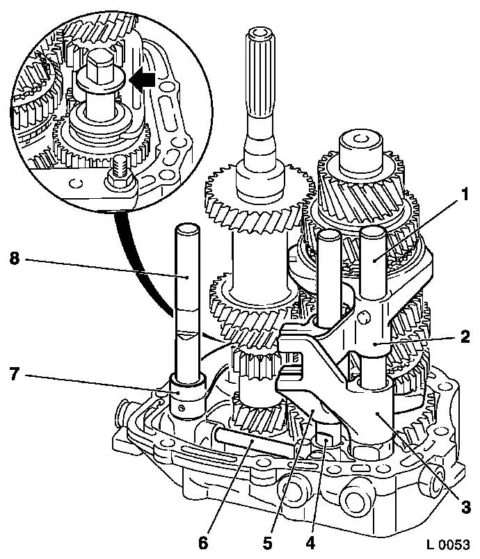
| 17. |
Remove shift fork, 3rd/4th gear and reverse gear
| • |
Drive roll pins out of 3rd/4th gear shift fork (3) and reverse
gear shift fork (6) using KM-308
|
| • |
Take out gearshift rod (2), gearshift rod reverse gear and
shift fork
|
|
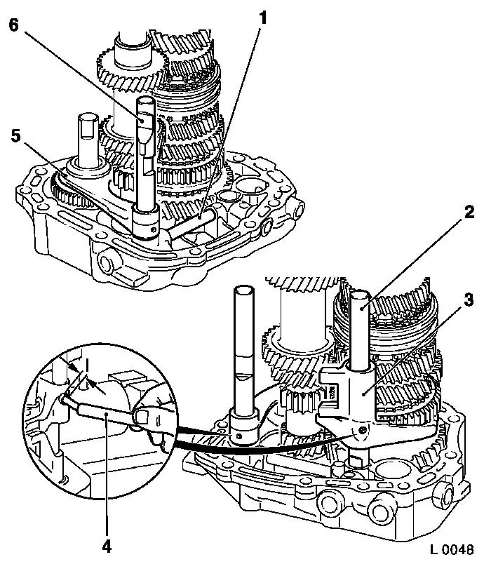
| 18. |
Remove gear shift driver
| • |
Remove 5th gear shift driver (4) from end shield
|
|
| 19. |
Remove locking pins (5)
| • |
Remove roll pin for catch from end shield
|
|
|

|
Important: Relieve pressure on
gearshift rod guides – for this, support gearshift rods (1)
above with wooden wedge (2)
|
| 20. |
Remove 1st/2nd gear shift fork
| • |
Drive roll pin (3) out of 1st/2nd gear shift fork (4) using
KM-308
|
| • |
Take out shift fork with gearshift rod
|
|
|
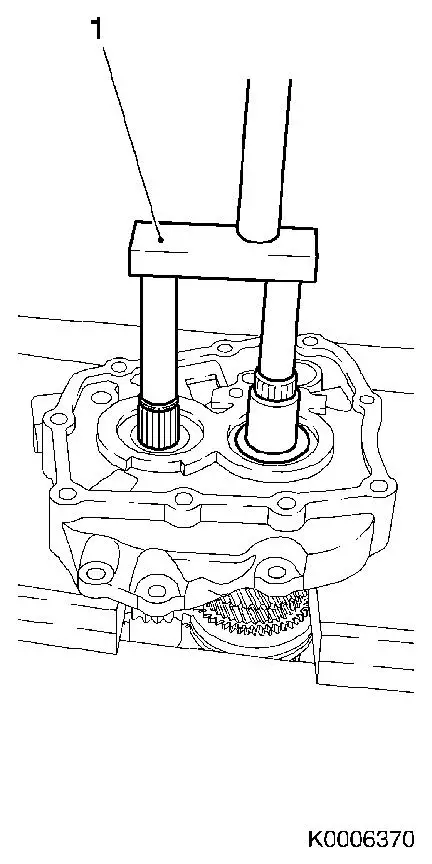
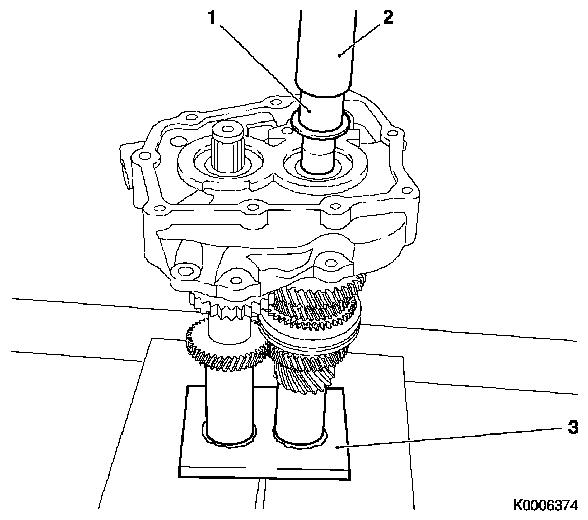
Important: Collect main shaft,
drive shaft and reverse idler.
|
| 21. |
Remove main shaft and drive shaft
| • |
Detach end shield from KM-552
|
| • |
Press main shaft and drive shaft out as shown using KM-6335 (1)
Note: To ensure that
both shafts are pushed out evenly, press harder on the main shaft
side. Take care that the gear wheel, 1st gear, is not in contact
with the press.
|
| • |
Collect main shaft, drive shaft and reverse idler
|
|
|
|
|
Important: Note that retaining
ball is released.
|
| 22. |
Remove reverse gear axle (1)
| • |
Clamp reverse gear spindle in vice
Note: Use protective
jaws.
|
| • |
Carefully knock off end shield with brass punch
|
|
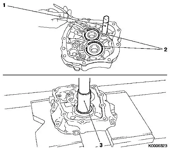
| 23. |
Remove bearing for main and drive shafts
| • |
Remove 2x retaining rings (2)
|
| • |
Press out 2x bearings using KM-500-5
(3)
|
|
|
| 24. |
Clean all parts and sealing surfaces
|
| 25. |
Check all parts
Note: Replace damaged
components.
|
 Install
| 26. |
Lubricate rotating parts on their bearing, running, seating,
and pressure surfaces using transmission fluid.
|
|
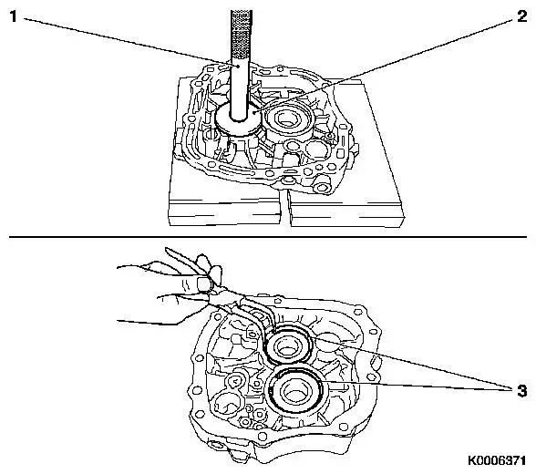
| 27. |
Install bearing for main and drive shafts
| • |
Press in 2x bearings using KM-523-1
(1) and KM-6336 (2)
|
| • |
Fit 2x retaining rings (3)
Note: Check retaining
ring for proper seating.
|
|
|
|
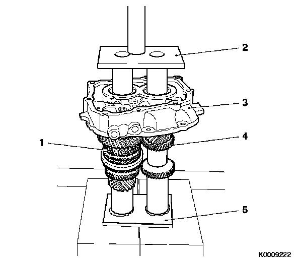
Important: Check shaft for proper
seating.
|
| 28. |
Fit main and drive shafts
| • |
Place main shaft (1) and drive shaft (4) on KM-6337 (5)
|
| • |
Place end shield (3) on main shaft and drive shaft and press on
with KM-6338 (2)
|
|
|
|
| 29. |
Fit 5th gear bearing sleeve (1)
| • |
Locate end shield on KM-6337 (3)
|
| • |
Press bearing sleeve on main shaft using KM-6339 (2)
|
|
|
|
Important: Note installation
position.
|
| 30. |
Fit reverse gear axle (1)
| • |
Locate reverse idler on axle
Note: Note installation
position, shift fork groove to top.
|
| • |
Press reverse gear axle with inserted lock ball (arrow) to stop
in end shield
|
|
|
|
| 31. |
Attach end shield to KM-552
|
| 32. |
Attach end shield to KM-113-2 using
KM-552
|
| 33. |
Fit locking pin (1)
| • |
Insert 3rd/4th gear and reverse gear locking pins
|
|
Important: To relieve pressure on
gearshift rod guides in end shield, support gearshift rods with
wooden wedge when securing with pin.
|
| 34. |
Fit reverse gear shift fork
| • |
Insert reverse gear shift fork (5) and gearshift rod (6)
|
| • |
Insert new roll pin using KM-308
(4)
Note: Allow new roll
pin to protrude approximately 2 mm/0.08 in (Dimension I).
|
|
Important: To relieve pressure on
gearshift rod guides in end shield, support gearshift rods with
wooden wedge when securing with pin.
|
| 35. |
Fit 1st/2nd gear shift fork
| • |
Insert 1st/2nd gear shift fork (3) and gearshift rod (2)
|
| • |
Insert new roll pin using KM-308
(4)
Note: Allow new roll
pin to protrude approximately 2 mm/0.08 in (Dimension I).
|
|
|
|
| 36. |
Insert 5th gear (4) shift driver.
|
Important: To relieve pressure on
gearshift rod guides in end shield, support gearshift rods with
wooden wedge when securing with pin.
|
| 37. |
Fit 3rd/4th gear shift fork
| • |
Insert 3rd/4th gear shift fork (2) and gearshift rod (1)
|
| • |
Insert new roll pin using KM-308
(3)
Note: Allow roll pin to
protrude approximately 2 mm.
|
|
| 38. |
Fit locking plugs
| • |
Install 4x locking plugs (5...7)
Note: Drive to stop
with plastic hammer or soft metal drift.
|
|
| 39. |
Bring gear shift fork into neutral speed position
|
|
|
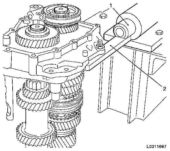
| 41. |
Attach bridge (2) for locking bolt on end shield
| • |
Screw in 2x new bolt
Note: Coat bolts with
locking compound
|
|
| 42. |
Move gearshift fork 1st/2nd gear into neutral
|
| 43. |
Fasten 2x bolt for bridge 7 Nm
|
| 44. |
Bring shift fork into neutral position.
|
| 45. |
Attach bearing support (4) to end shield with pawl (3)
| • |
Tighten 2x bolt 9 Nm
Note: Coat bolts with
locking compound
|
|
|
|
Important: Note installation
direction. Long gear hub points to end shield.
|
| 46. |
Install 5th gear (driven) (2)
| • |
Insert end shield with main and drive shafts in KM-6337 (3)
|
| • |
Press on 5th gear using KM-473
(1)
|
| • |
fit new retaining ring (4)
Note: Retaining ring
must engage completely.
|
|
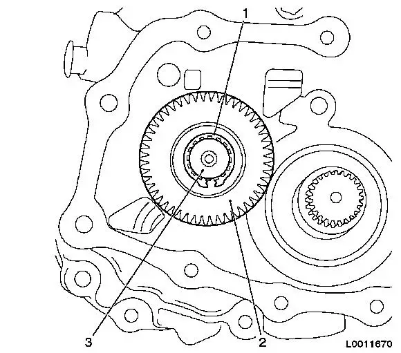
| 47. |
Fit 5th gear (5) (driven)
| • |
Coat needle bearings (6) with transmission fluid and place on
main shaft
Note: Ensure correct
seating of slotted needle bearings.
|
| • |
Locate 5th gear and 5th gear synchroniser ring on main
shaft
|
|
|
|
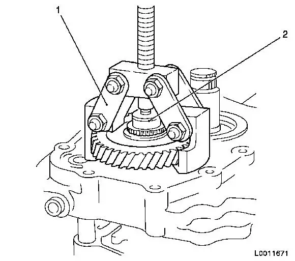
| 48. |
Press on 5th gear synchro body assembly
| • |
Insert end shield in KM-6337
|
| • |
Place synchro body assembly (1) on main shaft
|
Important: Synchroniser ring lugs
must be aligned with synchro body grooves.
|
| • |
Press synchro body in KM-473 on to
main shaft
|
| • |
fit new retaining ring (2)
Note: Retaining ring
must engage completely.
|
|
| 49. |
Fit bearing support with rocker arm
| • |
Insert 2x crosshead shoes (arrow) in 5th gear shift fork
(3)
|
| • |
Insert bearing support with rocker arm in end shield
|
| • |
Insert 2x bolts with locking compound
|
|
|
|
| 50. |
Install friction washer and magnet
| • |
Fit friction washer (arrow) on axle, reverse gear wheel, with
grease
|
| • |
Insert magnet with grease
|
|
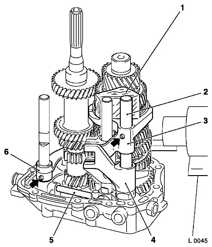
Important: Before installing end
shield, check following items for position and seating:
| 1. |
3rd/4th gear shift fork |
| 2. |
3rd/4th gear shift rod |
| 3. |
5th gear shift driver |
| 4. |
1st/2nd gear shift rod |
| 5. |
1st/2nd gear shift fork |
| 6. |
Lock pin for gear stop |
| 7. |
Reverse gear shift fork |
| 8. |
Reverse gear shift rod |
|
| 51. |
Detach end shield from KM-113-2
| • |
Detach end shield from KM-552
|
|
|
|
| 52. |
Install end shield (2)
|
| 53. |
Attach end shield cover (1)
|
|
| 54. |
Install front axle body
|
| 55. |
Detach KM-6001-B from front axle
body
|
|
| 56. |
Fit reversing lamp switch (3)
| • |
Tighten reversing lamp switch 20
Nm
|
| • |
Connect wiring harness plug (4) to reversing lamp switch
|
|
| 57. |
Install gearbox cover (1)
Note: For F17+
transmission.
Install gearshift module (2)
Note: For F17+ MTA
transmission.
|
|
|
