|
Replace shift/selector position sensor (M20
MTA)
 Remove Remove
Important: Follow Easytronic
safety guidelines .
Before carrying out any work on the M20-MTA high-pressure system,
it is essential that the MTA system pressure (approx. 40-60 bar) is
released.
|
| 1. |
Remove MTA system pressure
|
| 2. |
Remove battery support
|
| 3. |
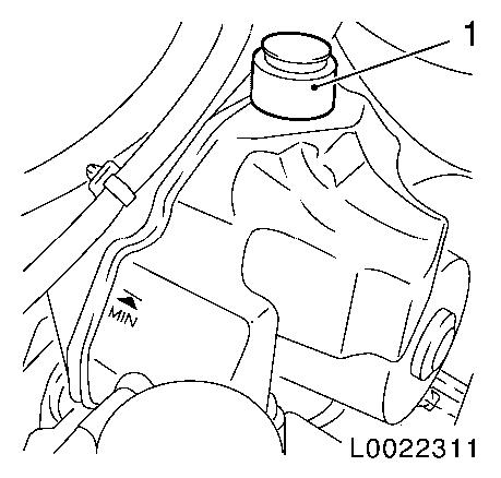
Bleed CS Speed oil reservoir
| • |
Unscrew closure cap (1)
|
| • |
Suction out CS Speed oil using a suitable tool
|
|
|
|
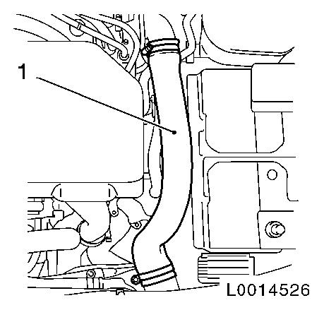
| 4. |
Remove the charge-air hose (1) from intercooler to connection
port on throttle valve housing
|
|
|
| 5. |
Detach bracket of MTA system high-pressure line (1)
|
|
|
| 6. |
Place collecting pan underneath.
|
| 7. |
Disconnect high-pressure line at clutch module
|
|
|
Important: The electronic control
unit may only be removed and reinstalled once. If the electronic
control unit is removed again, it must be replaced.
|
| 8. |
Remove electronic control unit 
|
| 9. |
Detach high-pressure line clamp at gearshift module bracket
|
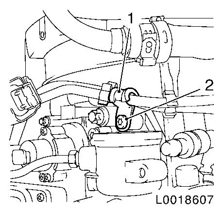
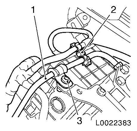
| 10. |
Unclip wiring harness (2) from high-pressure line (1)
|
|
|
| 11. |
Detach high-pressure line (1) from gearshift module
|
|
|
| 12. |
Remove shift (3) or selector position (1) sensor
Note: Note installation
position.
| • |
Release wiring harness plug (4) or (5) and disconnect
|
|
|

|
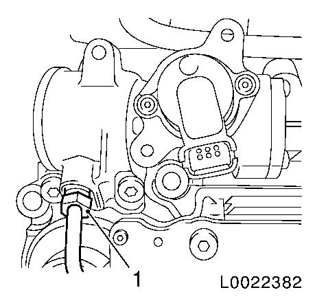
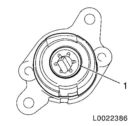
| 13. |
Pull shift/selection position sensor drive (1) out of gearshift
module
|
|
|
 Install
| 14. |
Install shift/selection position sensor drive
| • |
Lightly grease drive control arm
|
| • |
Set drive in correct installation position (1)
|
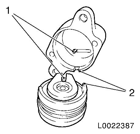
| • |
Insert drive in gearshift module and press in to the stop
Note: The mark on the
gearshift module and drive must align (2).
After pressing the drive into the gearshift module, ensure proper
seating by turning the drive.
Do not allow the drive pin for the sensor to become twisted.
|
|
|
|
| 15. |
Attach shift/selector position sensor
| • |
Position sensor on drive and tension spring in sensor by
turning clockwise (arrow)
|
| • |
Tighten 2x bolts 3.6 Nm
|
|
|

|
| 16. |
Fasten shift (3) or selector position (1) sensor
| • |
Tighten 2x bolts (2) 3.6 Nm
|
| • |
Connect and lock wiring harness plug (4) or (5)
|
|
|
|
| 17. |
Detach high-pressure line (1) from gearshift module
| • |
Tighten union nut (2) 14 Nm
|
|
|
|
| 18. |
Attach high-pressure line clamp at gearshift module bracket
|
| 19. |
Clip wiring harness (2) to high-pressure line (1)
|
|
|
Important: The electronic control
unit may only be removed and reinstalled once. If the electronic
control unit is removed again, it must be replaced.
|
| 20. |
Install electronic control unit
|
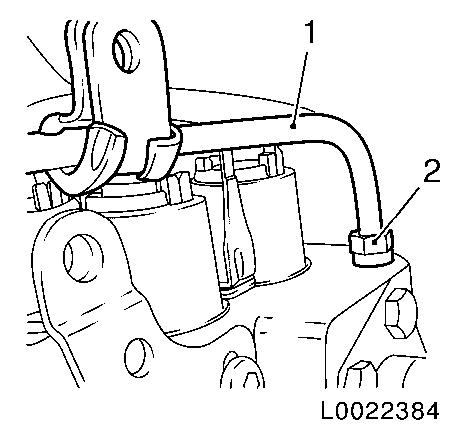
| 21. |
Connect high-pressure line to clutch module
| • |
Tighten union nut (1) 14 Nm
|
|
|
|
| 22. |
Fasten bracket of MTA system high-pressure line (1)
|
|
|
| 23. |
Fit the charge-air hose from intercooler to connection port on
throttle valve housing
| • |
Tighten 2x clamp 3.5 Nm
|
|
|
|
| 24. |
Fill CS Speed hydraulic fluid
Note: With the system
depressurised, fill the reservoir to just under the lower line of
the filler pipe.
|
| 25. |
Install battery support and battery
|
| 26. |
Necessary Start-Up Routines for Easytronic
|
| 27. |
Program volatile memories
|
|
