Engine Block Cleaning and Inspection
Special Tools
EN-8087 Gauge
For equivalent regional tools, refer to
Special Tools .
Cleaning Procedure
| 1. |
Remove any old thread sealant,
gasket material or sealant. |
| 2. |
Clean all the following areas
with solvent: |
| 3. |
Clean all threaded and through
holes with solvent. |
| 4. |
Dry the engine block with
compressed air. |
Visual Inspection
| 1. |
Inspect the crankshaft
bearings journals for damage or spun bearings. The crankshaft
bearing journals are not repairable, if the crankshaft bearing
journals are damaged the engine block assembly must be
replaced. |
| 2. |
Inspect all sealing and mating
surfaces for damage, repair or replace the engine block assembly if
necessary. |
| 3. |
Inspect all threaded and
through holes for damage or excessive debris. |
| 4. |
Inspect all bolts for damage,
if damaged replace with NEW bolts only. |
| 5. |
Inspect the cylinder walls for
cracks or damage. The cylinder sleeves are not serviced separately,
if the cylinders are damaged the cylinder block assembly must be
replaced. |
| 6. |
Inspect the engine block for
cracks. Do not repair any cracks. If cracks are found, the cylinder
block assembly must be replaced. |
Measuring Procedure
Engine Block Flatness Inspection
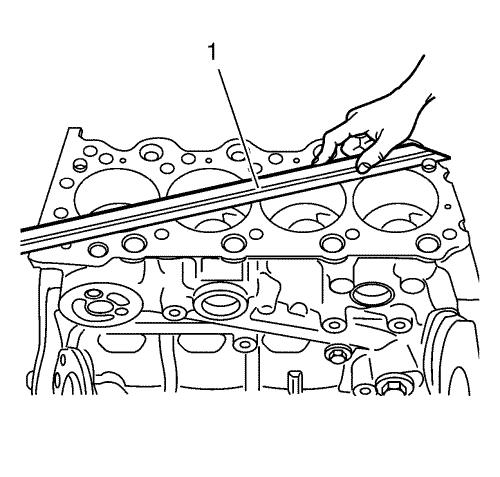
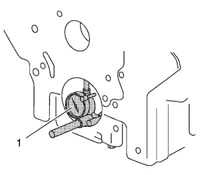
| 1. |
Inspect the engine block as
shown for distortion. Use a straightedge (1). |
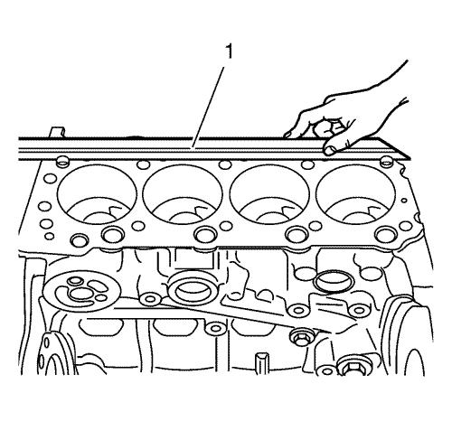
| 2. |
Inspect the engine block as
shown for deflection. Use a straightedge (1). |
Cylinder Sleeve Diameter Inspection
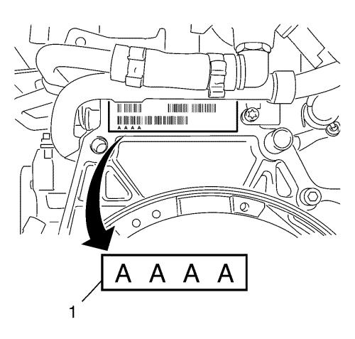
| 1. |
For classification the
cylinder bore diameters see marking of the cylinder bore
classification (1) on engine block. |
|
Note: If the cylinder
sleeve measurements are not within the recommended limits, ream the
cylinder bores with the recommended oversizes. Refer to
Engine Mechanical Specifications .
|
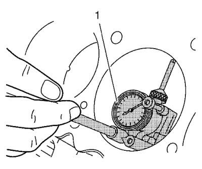
| 2. |
Inspect the cylinder bores
using the EN-8087 gauge (1). Inspect for the
following items: |
| |
• |
Wear of cylinder sleeve
|
| |
• |
Cylinder sleeve
diameter |
| |
• |
Tapering of cylinder
sleeve |
| |
• |
Oval status of cylinder
sleeve |
Bearing Bore Diameter In Cylinder Block Inspection
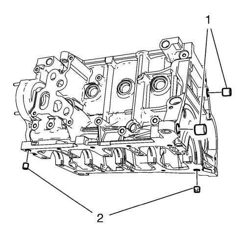
| 1. |
Install the 2 lower crankcase
location pins (2). |
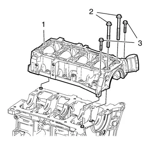
| 2. |
Install the lower crankcase
(1). |
|
Note: Install without
crankshaft and bearings for measure the bearing bore diameter in
cylinder block.
|
| 3. |
Loosely install the 10 lower
crankcase inner bolts (2). |
| 4. |
Loosely install the 10 lower
crankcase outer bolts (3). |
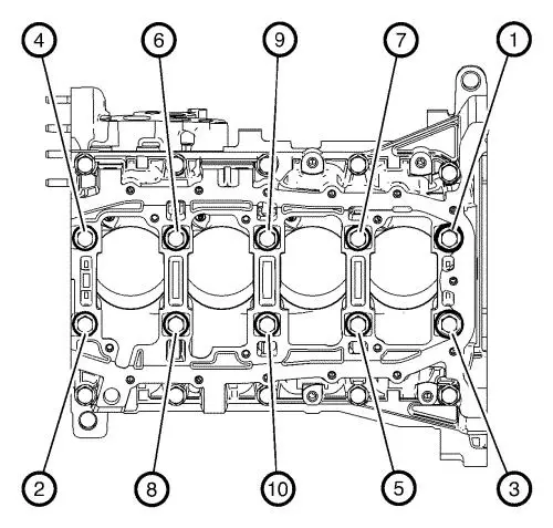
| 5. |
Tighten the 10 lower crankcase
inner bolts in sequence as shown and in the following order:
|
| |
• |
Tighten the bolts in sequence
as shown to 20 N·m (15 lb ft) |
| |
• |
Tighten in sequence as shown
to an additional 80° |
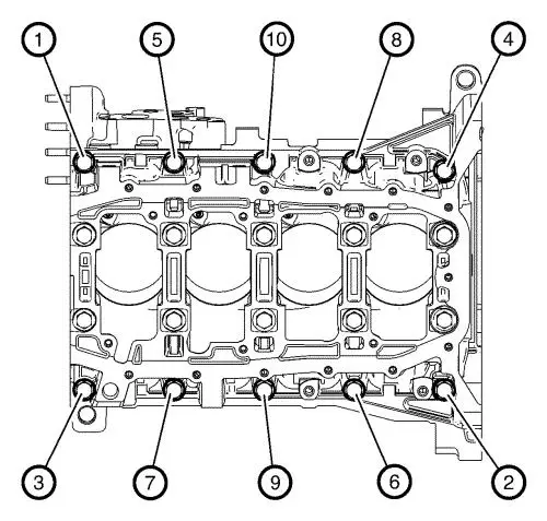
| 6. |
Tighten the 10 lower crankcase
outer bolts in sequence as shown to 30 N·m (22 lb
ft) . |
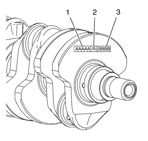
| 7. |
For classification the bearing
bore diameter in cylinder block see marking of the main bearing
journal diameter classification (1) on crankshaft. |
| 9. |
Remove the 10 lower crankcase
outer bolts (3). |
| 10. |
Remove the 10 lower crankcase
inner bolts (2). |
| 11. |
Remove the lower crankcase
(1). |
| 12. |
Remove the 2 lower crankcase
location pins (2). |
|
