Piston, Connecting Rod, and Bearing Cleaning and
Inspection
Visual Inspection And Cleaning Procedure
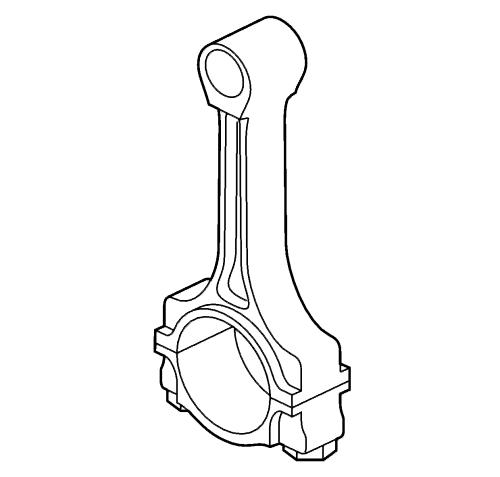
Connecting Rod
| 1. |
Clean the connecting rods in
solvent and dry with compressed air. |
| 2. |
Inspect the connecting rod for
the following: |
| |
• |
Signs of being twisted, bent,
nicked or cracked |
| |
• |
Scratches or abrasion on the
connecting rod bearing seating surfaces |
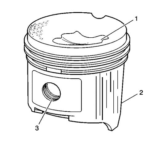
Piston
| 1. |
Clean the piston with a
cleaning solvent. DO NOT wire brush any parts of the piston.
|
| 2. |
Clean the piston ring
grooves. |
| 3. |
Inspect the piston on the
following: |
| |
• |
Cracked ring lands, skirts or
pin bosses |
| |
• |
Eroded areas on the top of the
piston (1) |
| |
• |
Scuffed or damaged skirts
(2) |
| |
• |
Worn piston pin bores
(3) |
| 4. |
If there is any excessive
wear, replace the piston. |
| 5. |
Measure the clearance between
piston pin and piston bore. Use the following procedure:
|
Piston And Connecting Rod Measurement Procedure
Piston Pin To Connecting Rod Bore And Piston Bore
Clearance
| 1. |
Measure clearance between
piston pin and connecting rod bore. Use the following
procedure: |
| |
1.1 |
Measure the piston pin outside
diameter. |
| |
1.2 |
Measure the connecting rod
bore diameter. |
| |
1.3 |
Substract the piston ring
diameter from the connecting rod diameter. |
| |
1.4 |
The clearance should be
0.019 mm-0.030 mm (0.0007 in-0.0012 in) .
|
| 2. |
If there is excessive
clearance, replace the piston pin. |
| 3. |
If there is still excessive
clearance, replace the connecting rod. |
| |
3.1 |
Measure the piston pin outside
diameter. |
| |
3.2 |
Measure the piston bore
diameter. |
| |
3.3 |
Substract the piston pin
diameter from the piston bore diameter. |
| |
3.4 |
The clearance should be
0.004 mm-0.014 mm (0.0002 in-0.0006 in) .
|
| 4. |
If there is excessive
clearance, replace the piston pin. |
| 5. |
If there is still excessive
clearance, replace the piston. |
Piston Ring Clearance
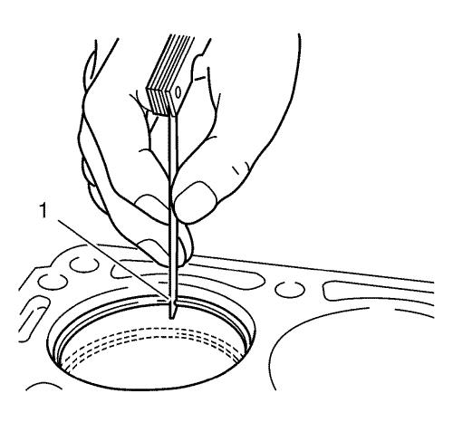
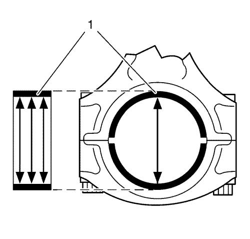
| 1. |
Install the piston rings to
the cylinder as shown (1) and measure the piston ring end gap.
Compare the measurements with those provided below: |
| |
• |
The upper compression ring end
gap should be 0.20 mm-0.30 mm (0.0078 in-0.0118
in) . |
| |
• |
The lower compression ring end
gap should be 1.00 mm-1.50 mm (0.0394 in-0.0591
in) . |
| |
• |
The oil ring end gap should be
0.25 mm-0.50 mm (0.0098 in-0.0197) . |
| 2. |
If the clearance is greater
than the provided specifications, the piston rings must be
replaced. |
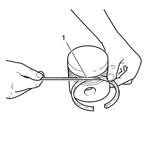
| 3. |
Measure the piston ring side
clearance as shown (1). Compare the measurements with those
provided below: |
| |
• |
The upper compression ring
side clearance should be 0.11 mm-0.15 mm (0.0043 in-0.0059
in) . |
| |
• |
The lower compression ring
side clearance should be 0.05 mm-0.09 mm (0.0020 in-0.0035
in) . |
| |
• |
The oil ring side clearance
should be 0.03 mm-0.07 mm (0.0012 in-0.0028 in)
. |
| 4. |
If the clearance is greater
than the provided specifications, replace the piston rings.
|
| 5. |
If the clearance is still to
great, replace the pistons. |
Connecting Rod Bearing Clearance (With Micrometer Gauge
Internal Measuring Device)
| 1. |
Install the connecting
bearings and the connecting rod bearing caps. |
| 2. |
Tighten the connecting rod
bearing cap bolts in the following sequence: |
|
Note: The old bolts can be
reused for the measuring procedure.
|
| |
2.1 |
Tighten the connecting rod
bearing cap bolts to 20 N·m (15 lb ft)
. |
| |
2.2 |
Tighten the bolts to an
additional 40° . |
| 3. |
Measure the connecting rod
bearing diameters at 3 points as shown (1). Use a internal
measuring device. |
| 4. |
Calculate the average
connecting rod inner diameter. |
| |
Formula: 1. result + 2. result + 3. result / 3 |
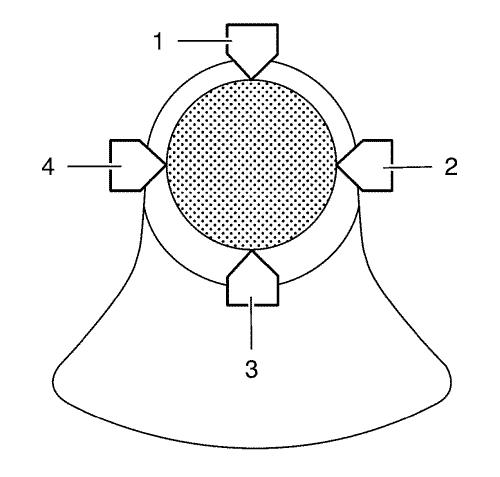
| 5. |
Measure the connecting rod
journal diameter at 2 points between (1) and (3) and between (2)
and (4). Use a micrometer gauge. |
| 6. |
Calculate the average
connecting rod journal diameter. |
| |
Formula: 1. result + 2. result / 2. |
| 7. |
Subtract the average
connecting rod journal diameter from the average connecting rod
bearing diameter in order to determine the connecting rod bearing
clearance. |
| |
The clearance should be 0.030 mm-0.062 mm (0.0012
in-0.0024 in) . |
|
