Camshaft Housing Cover Gasket Replacement (with Start/Stop
System)
Special Tools
| • |
GE-328-B
Sliding Hammer |
| • |
EN-48559
Protective Caps |
For equivalent regional tools, refer to
Special Tools .
Removal Procedure
Warning: Refer to
Gasoline/Gasoline Vapors Warning .
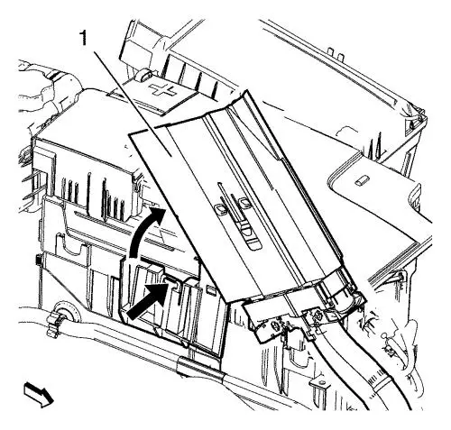
|
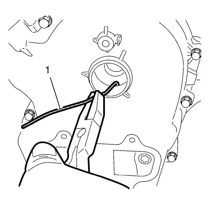
Note: Use a small
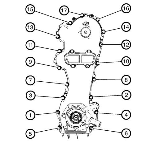
screwdriver to unclip the retainer clip (black arrow) and pull the
electronic control module out.
|
| 5. |
Remove the electronic control
module (1) from the battery tray. |
| 6. |
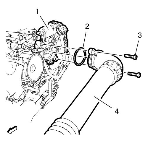
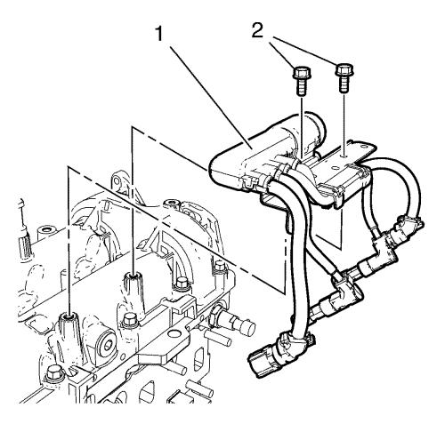
Remove the 2 charge air cooler
outlet air hose bolts (3). |
| 7. |
Remove the charge air cooler
outlet air hose bolt from the radiator inlet hose bracket.
|
| 8. |
Remove the charge air cooler
outlet air hose (4) from the throttle body (1) and hang
aside. |
| 9. |
Remove the charge air cooler
outlet air hose seal (2). |
| 10. |
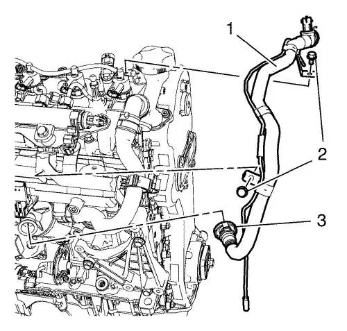
Disconnect the positive
crankcase ventilation pipe connector (3) from the positive
crankcase ventilation oil separator. |
| 11. |
Disconnect the positive
crankcase ventilation pipe connector wiring harness plug.
|
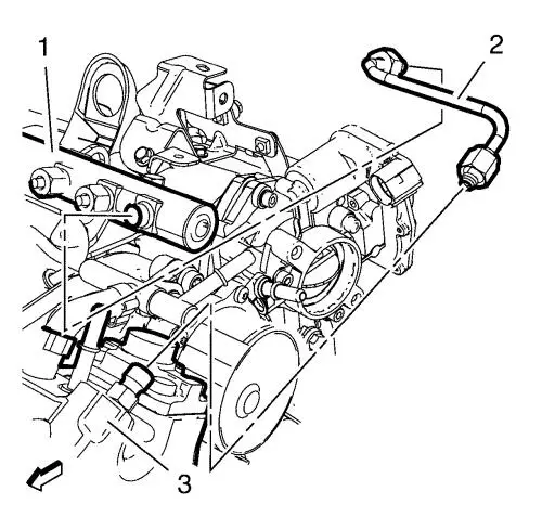
| 12. |
Remove the vacuum hose from
the turbocharger wastegate actuator vacuum control solenoid
valve. |
| 13. |
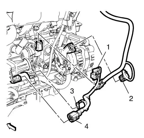
Remove the 2 positive
crankcase ventilation pipe bracket bolts (2). |
| 14. |
Remove the positive crankcase
ventilation pipe (1). |
| 15. |
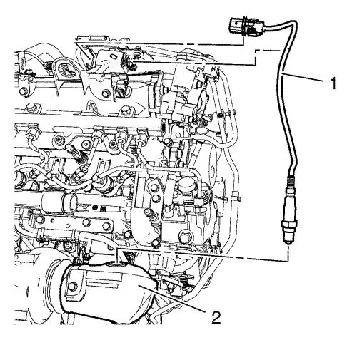
Unclip the oxygen sensor plug
from the exhaust pressure sensor bracket and the ECM wiring
harness. |
| 16. |
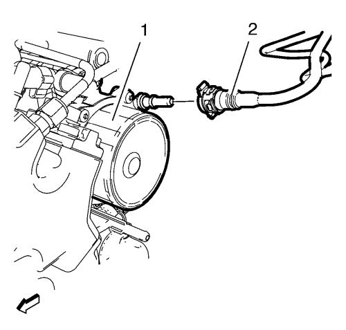
Remove the oxygen sensor (1)
from the catalytic converter (2). |
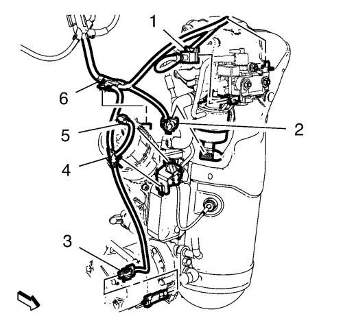
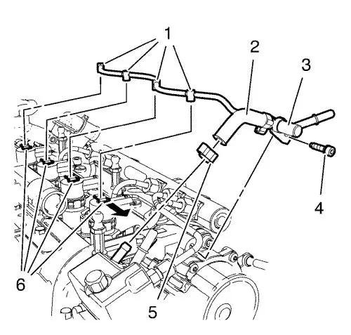
| 17. |
Disconnect the air
conditioning compressor wiring harness plug (3). |
| 18. |
Disconnect the exhaust
temperature sensor wiring harness plug (5). |
| 19. |
Unclip the retainer clip (4)
from the exhaust temperature sensor wiring harness bracket.
|
| 20. |
Disconnect the turbocharger
wastegate sensor wiring harness plug (2). |
| 21. |
Unclip the retainer clip (6)
from the oil filter housing. |
| 22. |
Disconnect the turbocharger
wastegate actuator vacuum control solenoid valve wiring harness
plug (1). |
| 23. |
Unclip the retainer clip from
the turbocharger wastegate actuator vacuum control solenoid valve
bracket. |
| 24. |
Disconnect the camshaft sensor
wiring harness plug (1) from the camshaft sensor (3). |
| 25. |
Unclip the 3 retainer clips
from: |
| |
• |
Engine lift bracket (5)
|
| |
• |
Engine sight shield stud
bracket (4) |
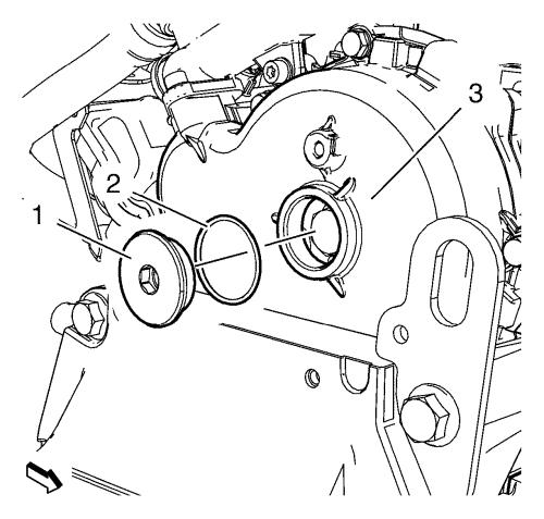
| 26. |
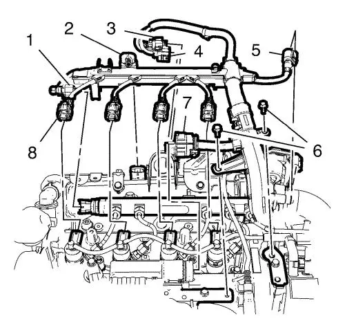
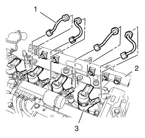
Disconnect the 4 fuel injector
wiring harness plugs (8). |
| 27. |
Disconnect the fuel rail
sensor wiring harness plug (1). |
| 28. |
Disconnect the manifold
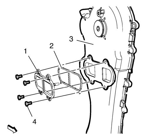
absolute pressure sensor wiring harness plug (2). |
| 29. |
Disconnect the oxygen sensor
wiring harness plug (3). |
| 30. |
Disconnect the exhaust
pressure sensor wiring harness plug (4). |
| 31. |
Disconnect the throttle body
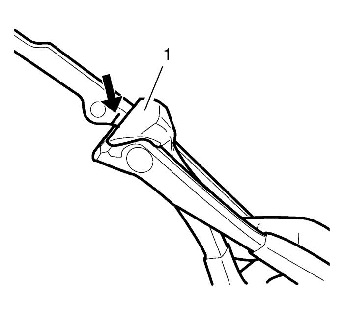
wiring harness plug (5). |
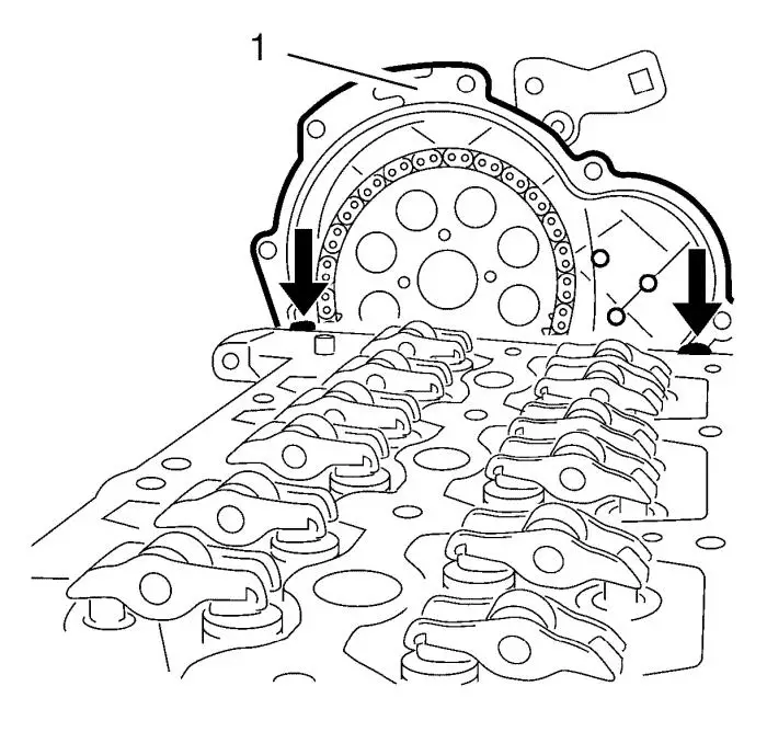
| 32. |
Remove the 2 wiring harness
bracket bolts (6). |
| 33. |
Unclip the ECM wiring harness
from the radiator inlet hose bracket. |
| 34. |
Disconnect the glow plug
wiring harness connector (7). |
| 35. |
Disconnect the engine coolant
temperature sensor wiring harness plug from the thermostat
housing. |
| 36. |
Disconnect the oil temperature
sensor wiring harness plug from the oil temperature sensor.
|
| 37. |
Disconnect the crankshaft
position sensor wiring harness plug from the crankshaft position
sensor. |
| 38. |
Disconnect the fuel injection
fuel pump wiring harness plug from the fuel injection fuel
pump. |
| 39. |
Disconnect the backup lamp
switch wiring harness plug from the backup lamp switch.
|
| 40. |
Unclip the wiring harness
retainer clips. |
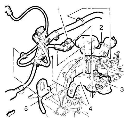
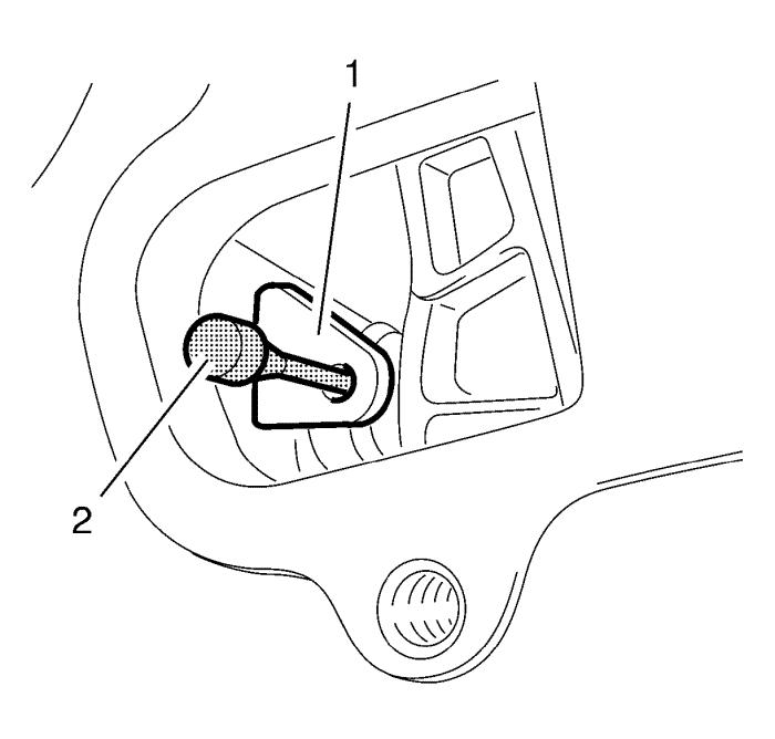
| 44. |
Unclip the generator wiring
harness clip from the exhaust gas recirculation valve vacuum tank
(2). |
| 45. |
Remove the turbocharger
wastegate actuator hose (1). |
| 46. |
Remove the turbocharger
wastegate actuator pipe (4). |
| 47. |
Remove the 2 exhaust gas
recirculation valve vacuum tank bolts (3). |
| 48. |
Remove the exhaust gas
recirculation valve vacuum tank (2). |
| 49. |
Disconnect the generator
wiring harness plug (2). |
| 50. |
Disconnect the exhaust gas
recirculation valve wiring harness plug (1). |
| 51. |
Disconnect the exhaust gas
recirculation cooler wiring harness plug (4). |
| 52. |
Remove the starter control
cable nut. |
| 53. |
Remove the starter control
cable (3). |
| 54. |
Unclip the wiring harness from
the oil level indicator tube. |
| 55. |
Unclip the wiring harness from
exhaust gas recirculation cooler. |
| 57. |
Hang the ECM wiring harness
aside. |
| 58. |
Remove the fuel feed pipe (1)
from the fuel injection pump (4). |
| 59. |
Remove the fuel return pipe
(2) from the fuel separator (3). |
| 60. |
Remove the brake booster
vacuum pipe (2) from the vacuum pump (1). |
| 61. |
Remove the turbocharger
wastegate actuator vacuum hose from the vacuum pump. |
| 62. |
Remove the fuel feed pipe (2)
from the fuel injection fuel pump (3) and the fuel rail (1).
|
| |
• |
Remove the fuel feed pipe nut
from the fuel rail. |
| |
• |
Remove the fuel feed pipe nut
from the fuel injection fuel pump. |
| 63. |
Unclip the 4 fuel injector
fuel return hose retainer springs (6). |
| 64. |
Remove the fuel injector fuel
return hose (1) from the 4 fuel injectors. |
| 65. |
Remove the fuel return hose
clamp (5). |
| 66. |
Remove the fuel return hose
(2) from the fuel injector pump. |
| 67. |
Remove the fuel separator bolt
(4). |
| 68. |
Remove the fuel injector fuel
return hose with the fuel separator (3). |
| 69. |
Loosen the 2 fuel rail
bolts. |
| 70. |
Remove the 4 fuel feed pipes
(1) from the 4 fuel injectors (3) and the fuel rail (2).
|
| |
• |
Remove the 4 fuel feed pipe
nut from the fuel rail. |
| |
• |
Remove the 4 fuel feed pipe
nut from the 4 fuel injectors. |
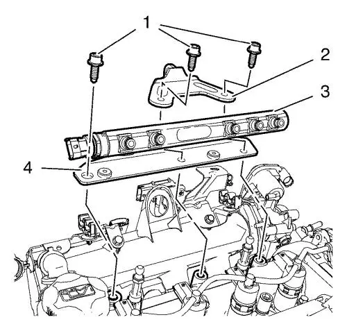
| 71. |
Remove the 3 fuel rail bracket
bolts (1). |
| 72. |
Remove the engine lift bracket
(2). |
| 73. |
Remove the fuel rail (3) with
the fuel rail bracket (4). |
| 74. |
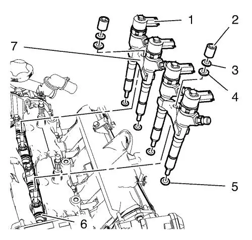
Remove the 2 fuel injector
bracket nuts (2). |
| 75. |
Remove the 2 fuel injector
conical washer (3). |
| 76. |
Remove the 2 fuel injector
spherical washers (4). |
|
Note: Injectors are
to be removed only in pairs. If the Injectors are not removed by
hand use the EN-46786 remover with
GE-328-B sliding hammer .
|
| 77. |
Remove the 4 fuel injectors
(1) with the 2 fuel injector brackets (7). |
| 78. |
Remove the 4 fuel injector
seals (5). |
| 79. |
Close the injector nozzles
with the EN-48559 protective caps . |
| 80. |
Remove the 2 glow plug wiring
harness bracket bolts (2). |
| 81. |
Remove the glow plug wiring
harness bracket (1). |
| 82. |
Remove the engine control
module wiring harness bracket bolt (2). |
| 83. |
Remove the engine control
module wiring harness bracket (1) left side. |
| 84. |
Remove the 2 engine control
module wiring harness bracket bolts (2). |
| 85. |
Remove the engine control
module wiring harness bracket (1) right side. |
| 86. |
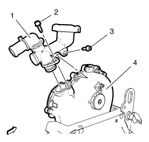
Remove the 2 oil filler tube
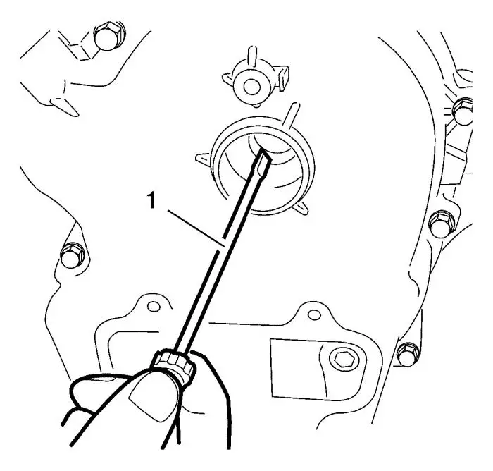
bolts (2, 3). |
| 87. |
Remove the oil filler tube (1)
from the oil pump housing (4). |
|
Note: The SPX
installation manual is supplied with the special tool and is also
available online from SPX directly. Go to
www.spxtools-shop.com.
|
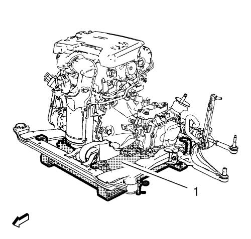
| 88. |
Assemble the CH-49290
engine support tool (1) according to the details provided in
the SPX installation manual. |
| 89. |
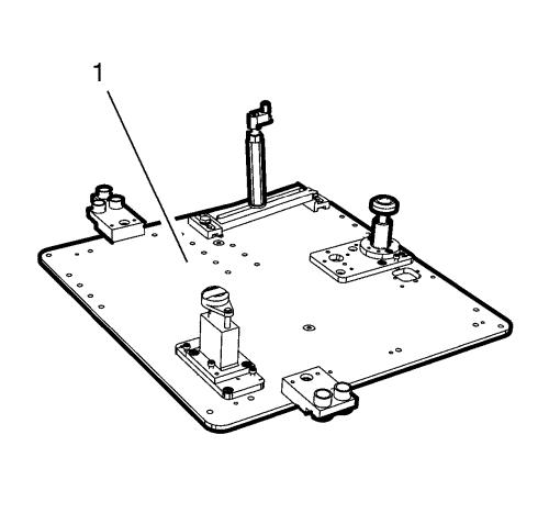
Support the CH-904
base frame on a jack. |
| 90. |
Support the CH-49290
engine support tool on the CH-904 base frame
. |
|
Note: The SPX
installation manual is supplied with the special tool and is also
available online from SPX directly. Go to
www.spxtools-shop.com.
|
| 91. |
Install the CH-49290
engine support tool (1) according to the details provided in
the SPX installation manual. |
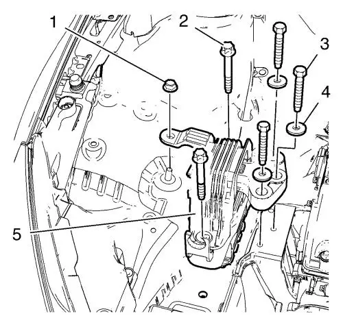
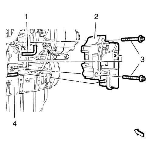
| 93. |
Remove the 3 engine mount to
engine mount bracket bolts (3) and the 3 washers (4). |
| 94. |
Remove the 2 engine mount to
body bolts (2) and the engine mount nut (1). |
| 95. |
Remove the engine mount
(5). |
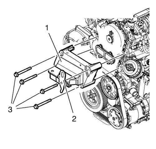
| 96. |
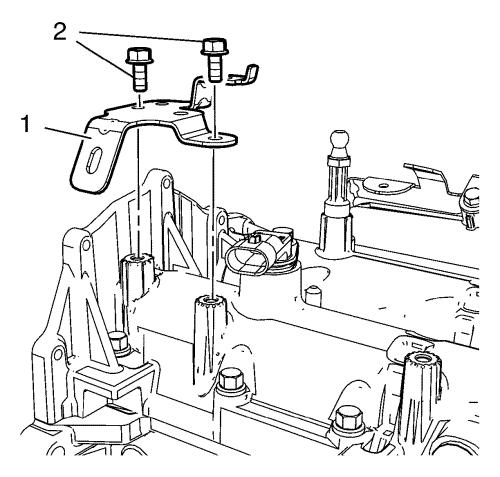
Remove 4 engine mount bracket
bolts (3). |
| 97. |
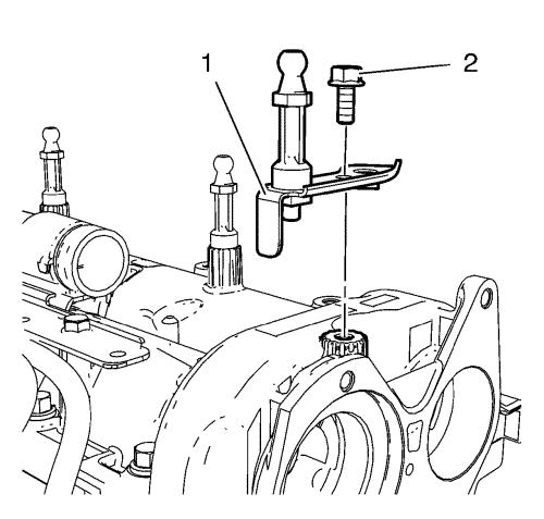
Remove engine lift bracket
(2). |
| 98. |
Remove engine mount bracket
(1). |
| 99. |
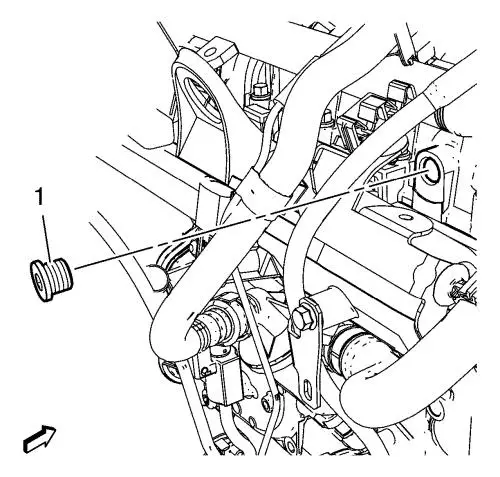
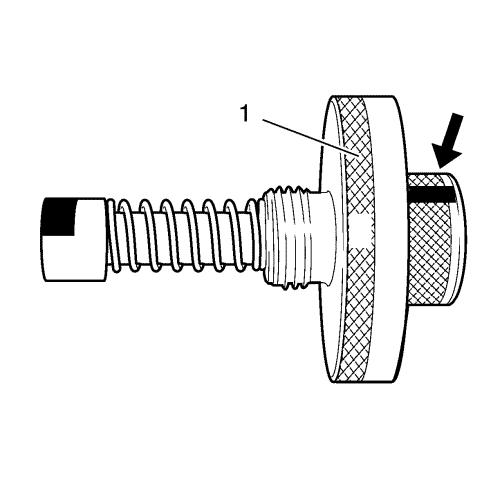
Remove the intake camshaft
housing core hole plug (1) from the camshaft housing. |
| 100. |
Clean the threads at the
camshaft housing and the camshaft housing core hole plug.
|
| 101. |
Mark (arrow) at the
EN-46781 fixing tool (1). |
|
Note: The
EN-46781 fixing tool (1) must be installed in
horizontal position.
|
| 102. |
Install the EN-46781
fixing tool (1) into the intake side. |
|
Note: If the
EN-46781 fixing tool does not rotate any longer,
the tool is correctly engaged.
|
| 103. |
Turn the crankshaft at the
crankshaft sprocket bolt carefully, until the EN-46781
fixing tool (1) engages at the intake camshaft. |
|
Note: Turn the
crankshaft carefully until EN-46785 fixing tool
engages in the flywheel.
|
| 105. |
Install the EN-46785
fixing tool (1). |
| 107. |
Remove the oil pump housing
plug (1) from the oil pump housing (3). |
| 108. |
Remove the oil pump housing
plug seal (2). |
| 109. |
Remove the 4 oil pump housing
closure cover bolts (4). |
| 110. |
Remove the oil pump housing
closure cover (1) from the oil pump housing (3). |
| 111. |
Remove the oil pump housing
closure cover gasket (2). |
|
Note: Do NOT remove
the camshaft sprocket bolt.
|
| 112. |
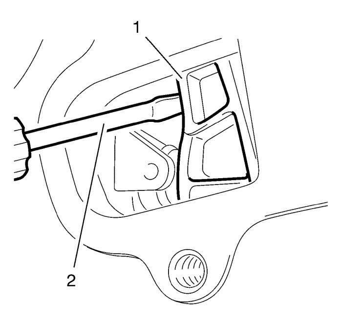
Loosen the camshaft sprocket
bolt. |
| 113. |
Tension the timing chain
tensioner (1). |
| 114. |
Fixing the timing chain
tensioner position with the EN-955-1 locking tool
(2). |
| 115. |
Remove the camshaft sprocket
bolt. |
| 116. |
Remove the camshaft sprocket
from the exhaust camshaft. Using a bent piece of rigid wire
(1). |
| 117. |
Remove the 5 oil pump housing
bolts from the oil pump housing (2) and camshaft housing.
|
|
Note: Take note that
there are different bolt lengths.
|
| 118. |
Remove the 16 camshaft housing
bolts (2). |
| 119. |
Remove the 2 camshaft housing
studs (1). |
|
Note: Carefully lever
the camshaft housing off timing case gasket with plastic wedge and
use a rubber mallet to knock it off the timing case. Place the
camshaft housing on suitable support.
|
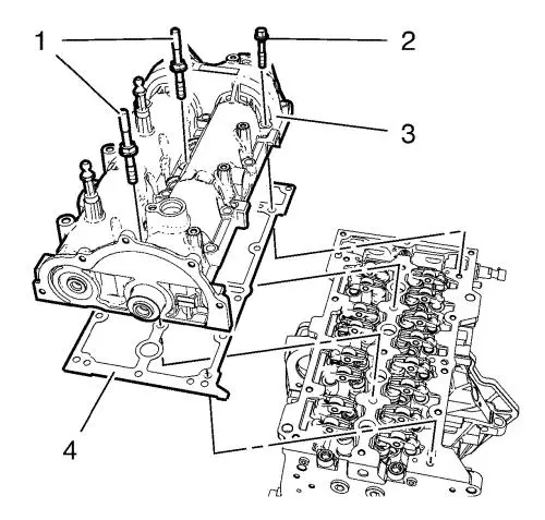
| 120. |
Remove the camshaft housing
(3). |
| 121. |
Remove the camshaft housing
gasket (4). |
Installation Procedure
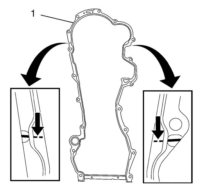
| 1. |
Remove the upper oil pump
housing gasket. |
| |
• |
Cut into the elastomer sealing
lips (arrows) using a sharp knife pressed against the cylinder
head. |
| |
• |
With a plastic spatula, loosen
the seal from the timing case and carefully snap it off at the
designated point (1). |
| |
• |
Remove the upper oil pump
housing gasket. |
|
Note: Make sure that
no residues remain at the joint between the timing case and
cylinder head, and that no bits of the gasket fall into the timing
case.
|
| 2. |
Remove any gasket residue and
clean all sealing surfaces thoroughly. |
| 3. |
Fit the NEW oil pump housing
gasket. (1). |
| |
Using a sharp knife, cut into the elastomer sealing lips
(arrows) at the breaking points of the new gasket. |
|
Note: It is essential
for the cutting tool (1) to have a straight cutting surface.
|
| 4. |
Cut the NEW oil pump housing
gasket off at the breaking points (arrow). |
|
Note: The upper new
gasket and the old lower gasket must not be allowed to overlap.
|
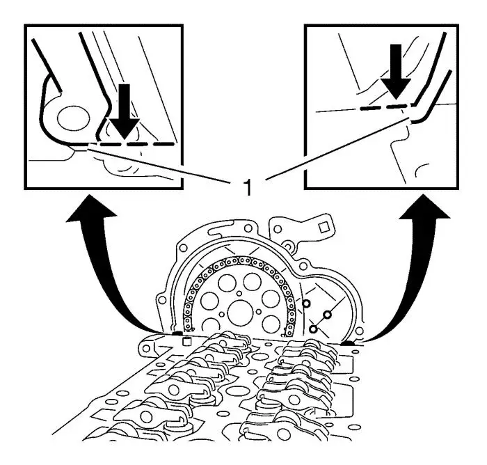
| 5. |
Fit NEW oil pump housing
gasket (1) to the contact surface between the cylinder block and
the timing case until the seal lies flush on the cylinder head and
timing case (arrows) and the holes in the gasket and the timing
case match up. |
| 6. |
Clean any oil and grease of
the exhaust camshaft, camshaft sprocket, camshaft sprocket bolt and
thread in exhaust camshaft. |
| 7. |
Clean all sealing
surfaces. |
| 8. |
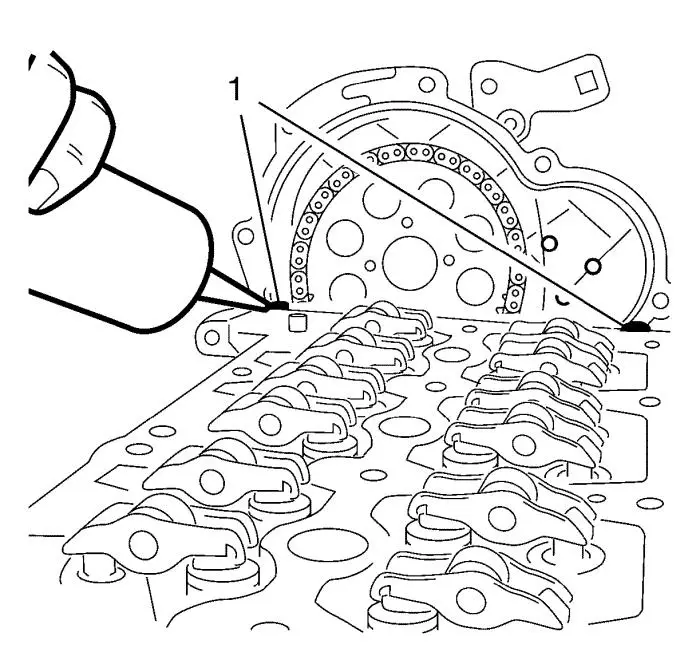
Apply silicone sealing
compound to the transitions between the cylinder head and oil pump
housing (1). |
| 9. |
Install NEW camshaft housing
gasket. |
| 10. |
Apply silicone sealing
compound to the transitions between the camshaft housing gasket and
oil pump housing. |
| 11. |
Install the camshaft housing
(3). |
|
Note: Tightening the
2 camshaft housing studs in sequence until the camshaft housing is
lying evenly on the cylinder head.
|
| 12. |
Loosely install the 2 camshaft
housing studs (1). |
|
Note: Mind at
different bolt length.
|
| 13. |
Loosely install the 16
camshaft housing bolts (2). |
| 14. |
Carefully align the camshaft
housing on the oil pump housing, using a rubber mallet.
|
| 15. |
Install the 5 oil pump housing
bolts (1) to the oil pump housing (2) and camshaft housing and
tighten the bolts carefully until the camshaft housing is in
contact with the oil pump housing. |
| 16. |
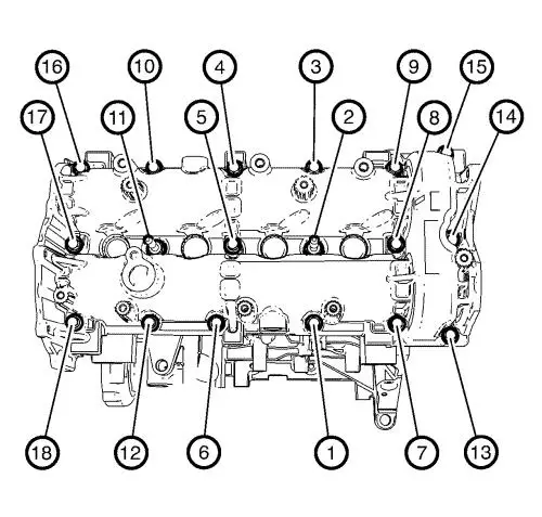
Tighten the 16 camshaft cover
bolts and the 2 camshaft cover studs in sequence as shown and first
step: |
| |
• |
For camshaft housing bolts M7
to 12 N·m (106 lb in) . |
| |
• |
For camshaft housing studs M8
to 15 N·m (11 lb ft) . |
| 17. |
Tighten the 16 camshaft cover
bolts and the 2 camshaft cover studs in sequence as shown and final
step: |
| |
• |
For camshaft housing bolts M7
to 18 N·m (13 lb ft) . |
| |
• |
For camshaft housing studs M8
to 25 N·m (18 lb ft) . |
| 18. |
Tighten the 5 oil pump housing
bolts (13 - 17) in sequence as shown: |
| |
• |
In first step and in sequence
as shown, tighten to 4 N·m (35 lb in)
. |
| |
• |
In second step and in sequence
as shown, tighten to 9 N·m (80 lb in)
. |
| 19. |
Install the camshaft sprocket
to the exhaust camshaft. |
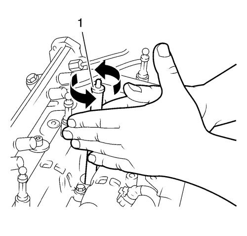
| |
• |
Using a suitable tool (1),
place the drive gear on the exhaust camshaft. |
| |
• |
Loosely install camshaft
sprocket bolt. |
| 20. |
Remove the EN-955-1
locking tool (2) from timing chain tensioner (1).
|
|
Note: A second
mechanical must tighten the timing chain tensioner (1) with a
suitable tool (2) while the timing chain is being tightened.
|
| 21. |
Tighten the camshaft sprocket
bolt to 150 N·m (111 lb ft) . |
| 22. |
Remove the EN-46785
fixing tool (1). |
| 23. |
Remove the EN-46781
fixing tool (1). |
| 24. |
Turn the crankshaft
720° (2 turns) in the direction of engine
rotation. |
| 26. |
Install the oil pump housing
closure cover gasket (2). |
| 27. |
Install the oil pump housing
closure cover (1) to the oil pump housing (3). |
| 28. |
Install the 4 oil pump housing
closure cover bolts (4) and tighten to 9 N·m (80 lb
in) . |
| 29. |
Install the oil pump housing
plug seal (2). |
| 30. |
Install the oil pump housing
plug (1) to the oil pump housing (3) and tighten to 9
N·m (80 lb in) . |
| 31. |
Install the intake camshaft
housing core hole plug (1) to the camshaft housing and tighten to
15 N·m (11 lb ft) . |
| 32. |
Install the engine mount
bracket (1). |
| 33. |
Install the engine lift
bracket (2). |
| 34. |
Install the 4 engine mount
bracket bolts (3) and tighten to 60 N·m (44 lb
ft) . |
| 35. |
Install the engine mount
(5). |
| 36. |
Install the 2 engine mount to
body bolts (2) and the engine mount nut (1) and tighten to
62 N·m (46 lb ft) . |
| 37. |
Install the 3 engine mount to
engine mount bracket bolts (3) and the 3 washers (4) and tighten to
62 N·m (46 lb ft) . |
| 39. |
Lower the CH-49290
engine support tool (1). |
| 40. |
Remove the CH-49290
engine support tool from CH-904 base frame
. |
|
Note: The SPX
installation manual is supplied with the special tool and is also
available online from SPX directly. Go to
www.spxtools-shop.com.
|
| 41. |
Disassemble the
CH-49290 engine support tool (1) according to the
details provided in the SPX installation manual. |
| 42. |
Install the oil filler tube
(1) to oil pump housing (4). |
| 43. |
Install the 2 oil filler tube
bolts (2, 3) and tighten to 9 N·m (80 lb
in) . |
| 44. |
Install the engine control
module wiring harness bracket (1) right side. |
| 45. |
Install the 2 engine control
module wiring harness bracket bolts (2) and tighten to 9
N·m (80 lb in) . |
| 46. |
Install the engine control
module wiring harness bracket (1) left side. |
| 47. |
Install the engine control
module wiring harness bracket bolt (2) and tighten to 9
N·m (80 lb in) . |
| 48. |
Install the glow plug wiring
harness bracket (1). |
| 49. |
Install the 2 glow plug wiring
harness bracket bolts (2) and tighten to 9 N·m (80
lb in) . |
| 50. |
Clean the injector sealing
surfaces in the cylinder head using EN-47632
cleaning tool (1) in following procedure: |
| |
• |
First take the brush side to
loosen the dirt. |
| |
• |
Second take the sponge side to
remove the dirt. |
| 51. |
Install the 4 NEW fuel
injector gaskets (6) to the camshaft housing. |
| 52. |
Remove the EN-48559
protective caps from the injector nozzles. |
| 53. |
Install the 4 NEW fuel
injector seals (5) to the fuel injectors. |
| 54. |
Install the 4 fuel injectors
(1) with the 2 fuel injector brackets (7). |
| 55. |
Install the 2 fuel injector
spherical washers (4). |
| 56. |
Install the 2 fuel injector
conical washer (3). |
| 57. |
Install the 2 fuel injector
bracket nuts (2) and tighten to 20 N·m (15 lb
ft) . |
| 58. |
Install the fuel rail (3) with
the fuel rail bracket (4). |
| 59. |
Install the engine lift
bracket (2). |
| 60. |
Install the 3 fuel rail
bracket bolts (1) and tighten to 25 N·m (18 lb
ft) . |
| 61. |
Install the 4 fuel injection
fuel feed pipes (1). |
| 62. |
Install the 4 fuel injection
fuel feed pipe nut M12 to 4 fuel injectors (3) and tighten to
24 N·m (18 lb ft) . |
| 63. |
Install the 4 fuel injection
fuel feed pipe nuts M14 to fuel rail (2) and tighten to 28
N·m (21 lb ft) . |
| 64. |
Tighten the 2 fuel rail bolts
to 25 N·m (18 lb ft) . |
| 65. |
Install the fuel injector fuel
return hose with the fuel separator (3). |
| 66. |
Install the fuel separator
bolt (4) and tighten to 9 N·m (80 lb in)
. |
| 67. |
Install the fuel return hose
(2) to the fuel injector pump. |
| 68. |
Install the fuel return hose
clamp (5). |
| 69. |
Install the fuel injector fuel
return hose (1) to the 4 fuel injectors. |
| 70. |
Clip in the 4 fuel injector
fuel return hose retainer springs (6). |
| 71. |
Install the fuel feed pipe (2)
to the fuel injection fuel pump (3) and the fuel rail (1).
|
| |
• |
Install fuel feed pipe nut M12
to fuel injection fuel pump and tighten to 24 N·m
(18 lb ft) . |
| |
• |
Install fuel feed pipe nut M14
to fuel rail and tighten to 28 N·m (21 lb
ft) . |
| 72. |
Install the turbocharger
wastegate actuator vacuum hose to the vacuum pump. |
| 73. |
Install the brake booster
vacuum pipe (2) to the vacuum pump (1). |
| 74. |
Install the fuel feed pipe (1)
to the fuel injection pump (4). |
| 75. |
Install the fuel return pipe
(2) to the fuel separator (3). |
| 76. |
Position the ECM wiring
harness. |
| 78. |
Clip in the wiring harness to
exhaust gas recirculation cooler. |
| 79. |
Clip in the wiring harness to
oil level indicator tube. |
| 80. |
Install the starter control
cable (3). |
| 81. |
Install the starter control
cable nut and tighten to 13 N·m (115 lb in)
. |
| 82. |
Connect the exhaust gas
recirculation cooler wiring harness plug (4). |
| 83. |
Connect the exhaust gas
recirculation valve wiring harness plug (1). |
| 84. |
Connect the generator wiring
harness plug (2). |
| 85. |
Install the exhaust gas
recirculation valve vacuum tank (2). |
| 86. |
Install the 2 exhaust gas
recirculation valve vacuum tank bolts (3) and tighten to 22
N·m (16 lb ft) . |
| 87. |
Install the turbocharger
wastegate actuator pipe (4). |
| 88. |
Install the turbocharger
wastegate actuator hose (1). |
| 89. |
Clip in the generator wiring
harness clip to the exhaust gas recirculation valve vacuum tank
(2). |
| 93. |
Clip in the wiring harness
retainer clips. |
| 94. |
Connect the backup lamp switch
wiring harness plug to the backup lamp switch. |
| 95. |
Connect the fuel injection
fuel pump wiring harness plug to the fuel injection fuel
pump. |
| 96. |
Connect the crankshaft
position sensor wiring harness plug to the crankshaft position
sensor. |
| 97. |
Connect the oil temperature
sensor wiring harness plug to the oil temperature sensor.
|
| 98. |
Connect the engine coolant
temperature sensor wiring harness plug to the thermostat
housing. |
| 99. |
Connect the glow plug wiring
harness connector (7). |
| 100. |
Clip in the ECM wiring harness
to the radiator inlet hose bracket. |
| 101. |
Install the 2 wiring harness
bracket bolts (6) and tighten to 9 N·m (80 lb
in) . |
| 102. |
Connect the throttle body
wiring harness plug (5). |
| 103. |
Connect the exhaust pressure
sensor wiring harness plug (4). |
| 104. |
Connect the oxygen sensor
wiring harness plug (3). |
| 105. |
Connect the manifold absolute
pressure sensor wiring harness plug (2). |
| 106. |
Connect the fuel rail sensor
wiring harness plug (1). |
| 107. |
Connect the 4 fuel injector
wiring harness plugs (8). |
| 108. |
Connect the camshaft sensor
wiring harness plug (1) to the camshaft sensor (3). |
| 109. |
Clip in the 3 retainer clips
to: |
| |
• |
Engine lift bracket (5)
|
| |
• |
Engine sight shield stud
bracket (4) |
| 110. |
Clip in the retainer clip to
the turbocharger wastegate actuator vacuum control solenoid valve
bracket. |
| 111. |
Connect the turbocharger
wastegate actuator vacuum control solenoid valve wiring harness
plug (1). |
| 112. |
Clip in the retainer clip (6)
to the oil filter housing. |
| 113. |
Connect the turbocharger
wastegate sensor wiring harness plug (2). |
| 114. |
Clip in the retainer clip (4)
to the exhaust temperature sensor wiring harness bracket.
|
| 115. |
Connect the exhaust
temperature sensor wiring harness plug (5). |
| 116. |
Connect the air conditioning
compressor wiring harness plug (3). |
| 117. |
Install the oxygen sensor (1)
to catalytic converter (2) and tighten to 45 N·m (33
lb ft) . |
| 118. |
Clip in the oxygen sensor plug
to exhaust pressure sensor bracket and ECM wiring harness.
|
| 119. |
Install the positive crankcase
ventilation pipe (1). |
| 120. |
Install the 2 positive
crankcase ventilation pipe bracket bolts (2) and tighten to
8 N·m (71 lb in) . |
| 121. |
Install the vacuum hose to
turbocharger wastegate actuator vacuum control solenoid
valve. |
| 122. |
Connect the positive crankcase
ventilation pipe connector wiring harness plug. |
| 123. |
Connect the positive crankcase
ventilation pipe connector (3) to the positive crankcase
ventilation oil separator. |
| 124. |
Install the charge air cooler
outlet air hose seal (2). |
| 125. |
Install the charge air cooler
outlet air hose (4) to the throttle body (1). |
| 126. |
Install the air cooler outlet
air hose bolt to the radiator inlet hose bracket and tighten to
10 N·m (89 lb in) . |
| 127. |
Install the 2 charge air
cooler outlet air hose bolts (3) and tighten to 10
N·m (89 lb in) . |
| 128. |
Install the electronic control
module (1) to the battery tray. |
|
