Valve Clearance Adjustment
Special Tools
For equivalent regional tools, refer to
Special Tools .
Removal Procedure
| 5. |
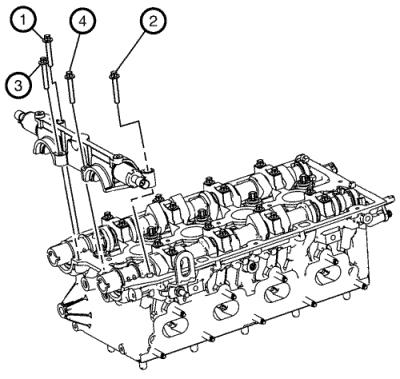
Remove the EN-6628-A
locking tool . |
Adjustment Procedure
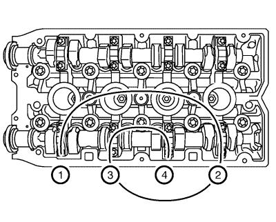
| 1. |
Inspect the 2 valve lash,
intake valve cylinder 1. |
| |
1.1 |
Turn the intake camshaft in
the direction of engine rotation by the camshaft hexagon until the
cams of cylinder 1 are in the test position. |
| |
1.2 |
Insert the EN-6361
gauge , inspect the valve clearance. |
| |
1.2 |
Write down the result.
|
| 2. |
Inspect the 2 valve lash,
intake valve cylinder 3. |
| |
2.1 |
Turn the intake camshaft in
the direction of engine rotation by the camshaft hexagon until the
cams of cylinder 3 are in the test position. |
| |
2.2 |
Insert the EN-6361
gauge , inspect the valve clearance. |
| |
2.2 |
Write down the result.
|
| 3. |
Inspect the 2 valve lash,
intake valve cylinder 4. |
| |
3.1 |
Turn the intake camshaft in
the direction of engine rotation by the camshaft hexagon until the
cams of cylinder 4 are in the test position. |
| |
3.2 |
Insert the EN-6361
gauge , inspect the valve clearance. |
| |
3.2 |
Write down the result.
|
| 4. |
Inspect the 2 valve lash,
intake valve cylinder 2. |
| |
4.1 |
Turn the intake camshaft in
the direction of engine rotation by the camshaft hexagon until the
cams of cylinder 2 are in the test position. |
| |
4.2 |
Insert the EN-6361
gauge , inspect the valve clearance. |
| |
4.2 |
Write down the result.
|
| 5. |
Inspect the 2 valve lash,
exhaust valve cylinder 4. |
| |
5.1 |
Turn the exhaust camshaft in
the direction of engine rotation by the camshaft hexagon until the
cams of cylinder 4 are in the test position. |
| |
5.2 |
Insert the EN-6361
gauge , inspect the valve clearance. |
| |
5.2 |
Write down the result.
|
| 6. |
Inspect the 2 valve lash,
exhaust valve cylinder 2. |
| |
6.1 |
Turn the exhaust camshaft in
the direction of engine rotation by the camshaft hexagon until the
cams of cylinder 2 are in the test position. |
| |
6.2 |
Insert the EN-6361
gauge , inspect the valve clearance. |
| |
6.2 |
Write down the result.
|
| 7. |
Inspect the 2 valve lash,
exhaust valve cylinder 1. |
| |
7.1 |
Turn the exhaust camshaft in
the direction of engine rotation by the camshaft hexagon until the
cams of cylinder 1 are in the test position. |
| |
7.2 |
Insert the EN-6361
gauge , inspect the valve clearance. |
| |
7.2 |
Write down the result.
|
| 8. |
Inspect the 2 valve lash,
exhaust valve cylinder 3. |
| |
8.1 |
Turn the exhaust camshaft in
the direction of engine rotation by the camshaft hexagon gear until
the cams of cylinder 3 are in the test position. |
| |
8.2 |
Insert the EN-6361
gauge , inspect the valve clearance. |
| |
8.2 |
Write down the result.
|
|
Note: Note the
removal sequence 1-4.
|
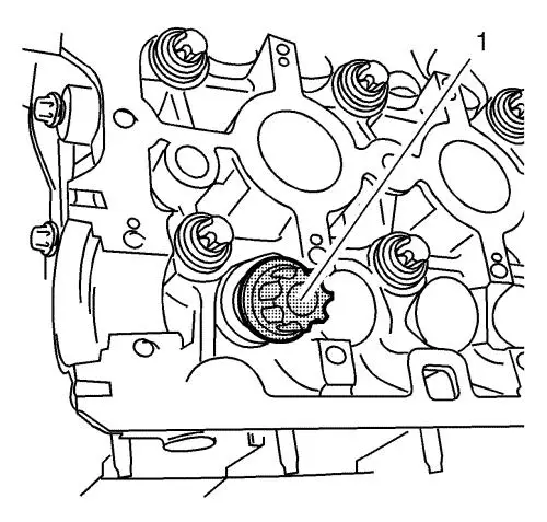
| 9. |
Remove the 4 camshaft bearing
support bolts. |
| 10. |
Release the bearing support by
striking it gently with a plastic hammer. |
| 11. |
Remove the 1st camshaft
bearing support (1). |
|
Note: Mark the
exhaust camshaft bearing caps before removal.
|
| 12. |
Loosen the 8 exhaust camshaft
bearing cap bolts working from outside to inside in a spiral in
steps of 1/2 up to 1 turn. |
| 13. |
Remove the 8 exhaust camshaft
bearing cap bolts. |
| 14. |
Remove the 4 exhaust camshaft
bearing caps Numbers 6-9 from the cylinder head. |
| 15. |
Remove the exhaust camshaft
(1). |
|
Note: Mark the intake
camshaft bearing caps before removal.
|
| 16. |
Loosen the 8 intake camshaft
bearing cap bolts working from outside to inside in a spiral in
steps of 1/2 up to 1 turn. |
| 17. |
Remove the 8 intake camshaft
bearing cap bolts. |
| 18. |
Remove the 4 intake camshaft
bearing caps Numbers 2-5 from the cylinder head. |
| 19. |
Remove the intake camshaft
(1). |
| 20. |
Using the EN-845
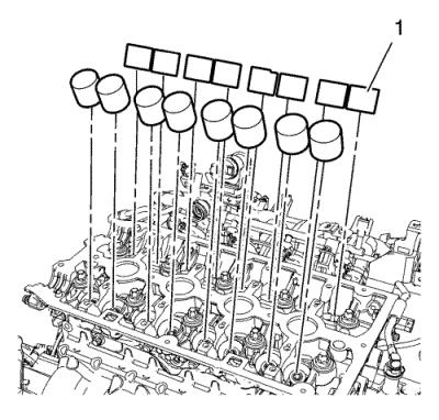
device (1), remove the 16 valve tappets. |
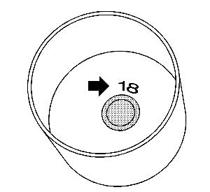
| 21. |
Example for determine valve
tappet size. |
| |
21.1 |
Measurement of the cup tappet
installed 3.12 mm (0.123 in) , identification
number 12. |
| |
21.2 |
Measured value between cams
and cup tappets +0.31 mm (0.012 in) = 3.43 mm
(0.135 in) . |
| |
21.3 |
Required value, intake valve
lash - 0.25 mm (0.010 in) . |
|
Note: The identification
number, arrow, is on the inside of the valve tappet.
|
| |
21.4 |
Measurement of the new cup
tappet = 3.18 mm (0.125 in) , identification
number 18. |
| |
21.5 |
Use a valve tappet with this
dimension or one that is nearest to it. |
| 23. |
Refer to Electronic Parts
Catalogue for the valve tappers sizes. |
Installation Procedure
|
Note: Observe the
correct assignment.
|
|
Note: Coat the
sliding surfaces with NEW engine oil.
|
| 1. |
Install the 16 tappets (1),
using the EN 845 suction device . |
|
