Steering Gear Replacement (Electronic Power Steering)
Special Tools
| • |
CH-49289
Centering Frame |
For equivalent regional tools, refer to
Special Tools .
Removal Procedure
|
Caution: With wheels of the vehicle facing straight ahead, secure
the steering wheel utilizing steering column anti-rotation pin,
steering column lock, or a strap to prevent rotation. Locking of
the steering column will prevent damage and a possible malfunction
of the SIR system. The steering wheel must be secured in position
before disconnecting the following components:
| |
|
• |
The intermediate shaft(s) |
After disconnecting these components, do not
rotate the steering wheel or move the front tires and wheels.
Failure to follow this procedure may cause the SIR coil assembly to
become un-centered and cause possible damage to the SIR coil. If
you think the SIR coil has became un-centered, refer to your
specific SIR coil's centering procedure to re-center SIR
Coil. |
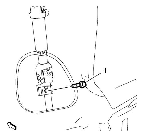
| 2. |
Remove the lower steering
intermediate shaft bolt (1). |
| 3. |
Detach the steering
intermediate shaft from the steering gear. |
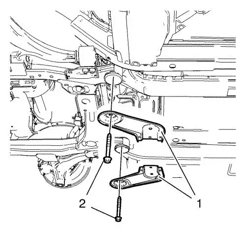
| 10. |
Remove and DISCARD the lower
stabilizer link shaft nut (2) on both sides. |
| 11. |
Remove stabilizer shaft link
(1) from stabilizer shaft. |
| 12. |
Remove stabilizer link shaft
(1) from stabilizer. |
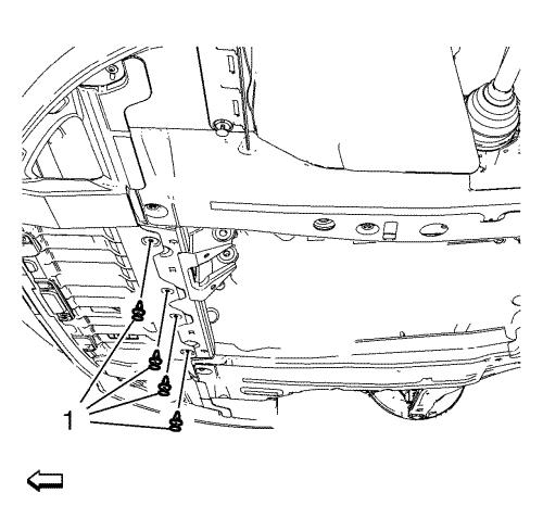
| 13. |
Remove 4 fasteners (1) of
engine side cover on both sides. |
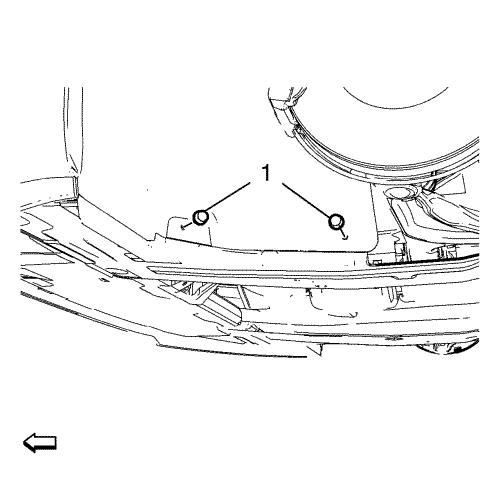
| 14. |
Remove 4 fasteners (1) of
front engine compartment cover. |
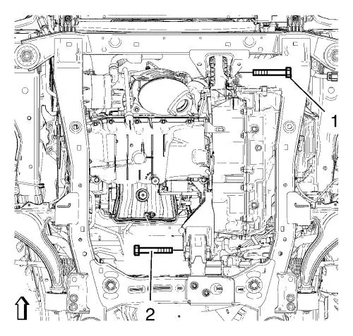
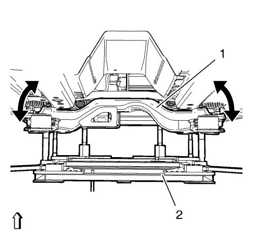
| 15. |
Remove the front (1) and the
rear (2) transmission mount bracket bolts. |
|
Note: The SPX
installation manual is supplied with the special tool and is also
available online from SPX directly. Go to
www.spxtools-shop.com.
|
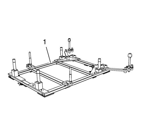
| 16. |
Assemble the CH-49289
centering frame (1) according to the details provided in the
SPX installation manual. |
| 17. |
Support the CH-904
base frame on a jack. |
| 18. |
Support the CH-49289
centring frame on the CH-904 base frame
. |
|
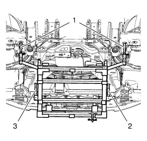
Note: Positioning
pins (2, 3) of CH-49289 adapter MUST stick into
holes of suspension frame.
|
|
Note: The SPX
installation manual is supplied with the special tool and is also
available online from SPX directly. Go to
www.spxtools-shop.com.
|
| 19. |
Install the CH-49289
centring frame according to the details provided in the SPX
installation manual. |
| 20. |
Check if wheel alignment is
required. |
| |
Move out positioning pins (1) and try to insert into underbody
holes. If guide pins can NOT be inserted, the
Wheel Alignment Measurement is required after installation of
the suspension frame. |
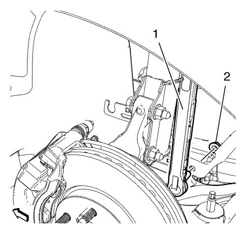
| 21. |
Remove 2 rear suspension frame
bolts (2). |
| |
Remove rear frame reinforcements (1). |
| 22. |
Lower the front suspension
frame assembly. Lower the suspension frame max. 55 mm
(2.165 in) . Bent the engine side cover aside.
|
|
Note: Connector
latches are difficult to access
|
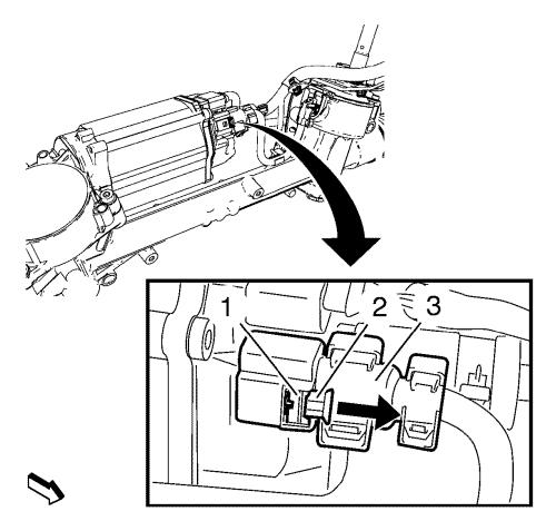
| 23. |
Disconnect electrical
connector (3). |
| |
23.1 |
Release the lock (2) by moving
in direction of arrow, use suitable screwdriver. |
| |
23.2 |
Push down the latch (1) and
pull off the electrical connector, use suitable screwdriver.
|
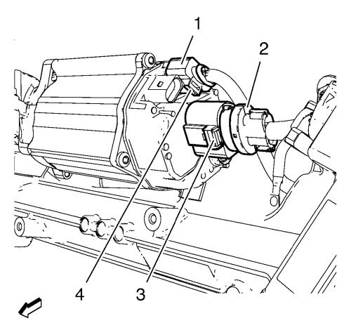
| 24. |
Disconnect electrical
connector (2). |
| |
24.1 |
Gently lift latch (3), using
angled screwdriver. |
| |
24.2 |
Pull off electrical connector
(2). |
| 25. |
Disconnect electrical
connector (1). |
| |
25.1 |
Gently lift latch (4), using
angled screwdriver. |
| |
25.2 |
Pull off electrical connector
(1). |
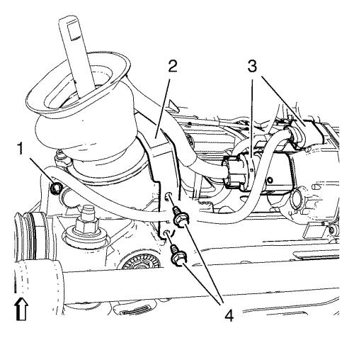
| 26. |
Carefully disconnect 2 wiring
harness plugs (3) from the steering gear with a suitable
tool. |
| 27. |
Remove 2 wiring harness
bracket bolts (4). |
| 28. |
Remove bracket (2) from
vehicle. |
| 29. |
Remove wiring harness retainer
(1) from steering gear. |

| 30. |
Remove and DISCARD the 2 right
stabilizer shaft (1) insulator clamp bolts (2). |
| |
Suspend stabilizer shaft (1) to body. |
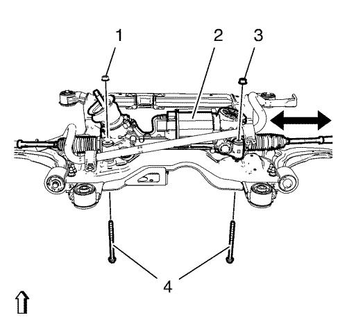
| 31. |
Remove and DISCARD the 2
steering gear bolts (4) and nuts (1, 3) from front suspension
frame. |
| 32. |
Carefully remove steering gear
(2) through right wheel house. |
| 33. |
Replace assembly parts if
necessary: |
Installation Procedure
|
Caution: Ensure that the steering column dash seal is installed
properly onto steering gear rack pinion housing. The sealing lip
MUST rest on lower steering column cover surface evenly. To ease
installation of the seal, apply liquid soap to the sealing lip.
After installation, verify that the seal lip does not protrude into
the vehicle's interior. Improper installation could result in poor
sealing performance and water intrusion into the vehicle.
|
|
Note: Check correct
wiring routing in order to assure correct installation.
|
| 1. |
Carefully insert steering gear
(2) through right wheel house and position steering gear into
installation position. |
| 2. |
Tighten the NEW steering gear
bolts (4) and nuts (1, 3) a first pass to 110 N·m
(81 lb ft) . |
| 3. |
Tighten the NEW steering gear
bolts (4) and nuts (1, 3) a final pass to an additional 150
- 165 degrees , using the EN-45059 meter
. |
| 4. |
Install and tighten 2 wiring
harness bracket bolts (4) to 9 N·m (80 lb
in) . |
| 5. |
Tighten wiring harness
retainer (1) to steering gear. |
|
Note: Connector
latches are difficult to access
|
| 6. |
Connect electrical connector
(1) until you hear it clicks. |
| 7. |
Connect electrical connector
(2) until you hear it clicks. |
|
Note: Connector
latches are difficult to access
|
| 8. |
Connect electrical connector
(3) until you hear it clicks. |
| 9. |
Push back lock (2) in opposite
direction of arrow until you hear it clicks. |
| 10. |
Position stabilizer shaft (1)
and bracket onto suspension frame. |
| 11. |
Install and tighten the NEW
right stabilizer shaft insulator clamp bolts (2) a first pass to
22 N·m (16 lb ft) . |
| 12. |
Tighten the NEW stabiliser
shaft insulator clamp bolts (2) a final pass to an additional
30 degrees , using the EN-45059
meter . |
| 13. |
Raise the frame (1) carefully,
using CH 49289 centering frame (2). |
|
Note: Positioning
pins (1) of CH-49289 centring frame MUST be
extended in order to guide into underbody holes.
|
| 14. |
Check for proper position of
the suspension frame by inserting the positioning pins (1) into the
underbody holes. |
| 15. |
Install the frame
reinforcements (1). |
| 16. |
Install the frame rear bolts
(2) and tighten to 160 N·m (118 lb ft)
. |
|
Note: The SPX
installation manual is supplied with the special tool and is also
available online from SPX directly. Go to
www.spxtools-shop.com.
|
| 17. |
Lower the CH-49289
centring frame (1) with the CH-904 base
frame and a jack. |
| 18. |
Remove the CH-49289
centring frame from the CH-904 base frame
. |
| 19. |
Disassemble the
CH-49289 centering frame (1) according to the
details provided in the SPX installation manual. |
| 20. |
Install the front transmission
mount bolt (1) and tighten to 58 N·m (43 lb
ft) . |
| 21. |
Install the rear transmission
mount bracket bolt (2) and tighten to 100 N·m (74 lb
ft) . |
| 22. |
Install and tighten 4
fasteners (1) of engine side cover on both sides. |
| 23. |
Install and tighten 4
fasteners (1) of front engine compartment cover. |
| 28. |
Install and tighten the NEW
lower stabilizer link shaft nut (2) on both sides to 65
N·m (48 lb ft) . |
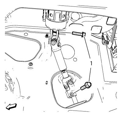
| 30. |
Install the lower intermediate
steering shaft bolt and tighten to 34 N·m (26 lb
ft) . |
|
