Control Valve Body Replacement
Removal Procedure
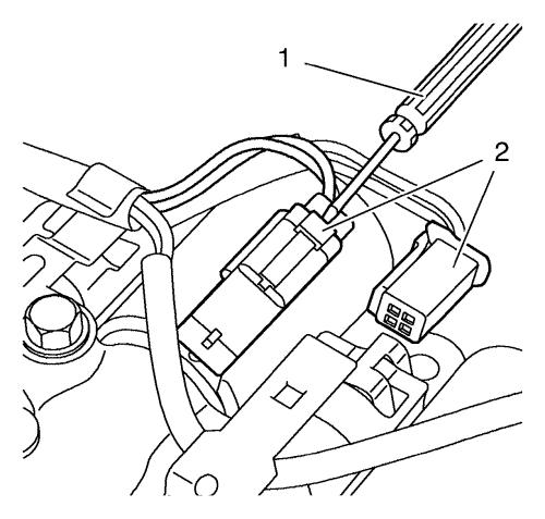
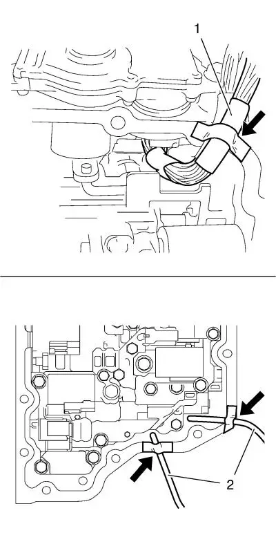
| 2. |
Disconnect the electrical
connectors of the solenoid valves. The illustration shows how to
use a screwdriver (1) for disconnecting the different connectors
(2). |
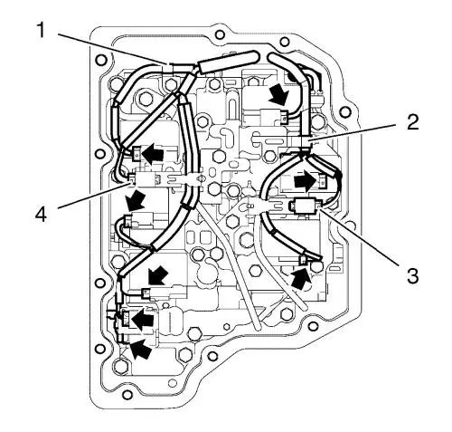
| 3. |
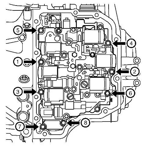
Disconnect 8 electrical
connectors (arrows) of the solenoid valves. |
| 4. |
Disconnect 2 electrical
connectors of the speed sensors (3, 4). |
| 5. |
Detach wiring harness from 2
retaining clamps (1, 2). |
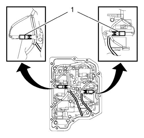
| 6. |
Remove 2 wiring harness speed
sensors from the control valve body. |
| |
Detach 2 electrical connectors speed sensor (1) from retainer
on the control valve body. |
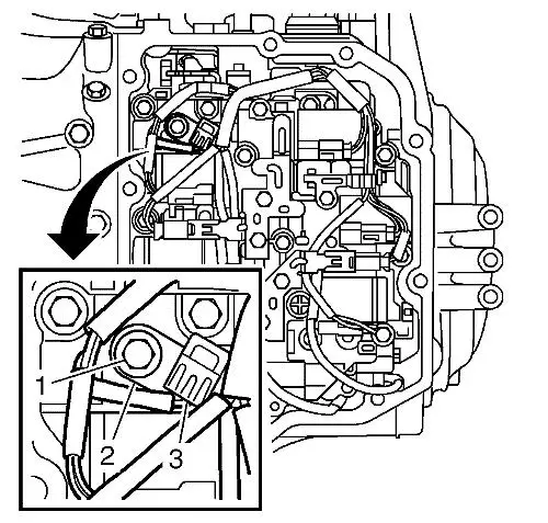
| 7. |
Remove the temperature sensor
bolt (1). |
| |
Remove the retaining plate (2). |
| |
Remove the temperature sensor (3). |
| 8. |
Move the wiring harness of the
solenoid valves (1) and the wiring harness of the speed sensors (2)
aside and secure the wiring harness with adhesive tape
(arrows). |
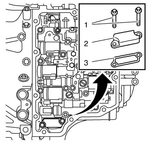
| 9. |
Remove the cover bolts
(1). |
| 10. |
Remove the cover (2).
|
| 11. |
Remove and DISCARD the gasket
(3). |
| 12. |
Loose the valve body.
|
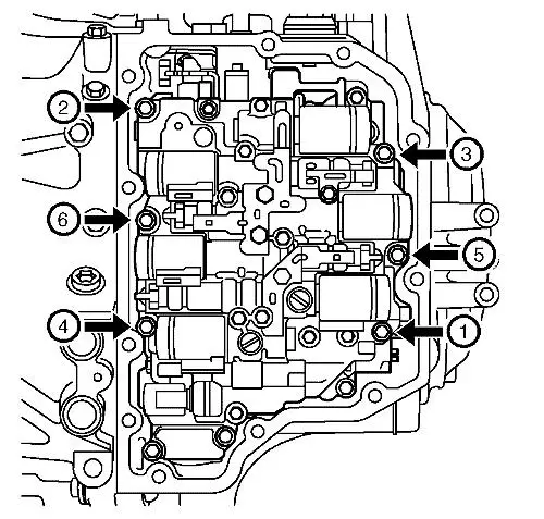
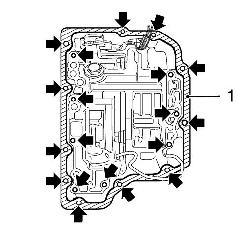
| 13. |
Loose the control valve body
bolts (arrows) in the sequence shown. |
| 14. |
Remove and DISCARD the control
valve body bolts. |
|
Note: The ducts are
filled with oil.
|
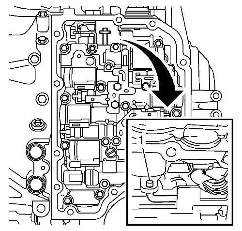
| 15. |
Remove the control valve body
carefully. |
| |
Unhook the connecting rod (1). |
Installation Procedure
| 1. |
Clean the sealing surface
(1). |
| 2. |
Clean 19 threads of the
control valve body and the control valve body cover holes
(arrows). |
| 3. |
Install the control valve
body. |
| 4. |
Hook in the connecting rod
(1). |
| 5. |
Install 6 NEW control valve
body bolts, but do not tighten yet. |
| 6. |
Install a NEW gasket
(3). |
| 7. |
Install the cover (2).
|
| 8. |
Install 2 cover bolts (1), but
do not tighten yet. |
| 9. |
Tighten the 8 control valve
body bolts (arrows) in the sequence shown to 10 N·m
(88 lb in) . |
| 10. |
Install the temperature sensor
(3). |
| 11. |
Coat the temperature sensor
O-ring with transmission fluid. |
| 12. |
Install the retaining plate
(2). |
| 13. |
Install the temperature sensor
bolt (1) and tighten to 10 N·m (88 lb in)
. |
| 14. |
Remove the adhesive tape
(arrows) and place the wiring harness of the solenoid valves (1)
and the wiring harness of the speed sensors (2) into the correct
position. |
| 15. |
Install 2 wiring harness speed
sensors to the control valve body. |
| |
Attach 2 electrical connectors speed sensor (1) to the retainer
on the control valve body. |
| 16. |
Attach wiring harness to 2
retaining clamps (1, 2). |
| 17. |
Connect 2 electrical
connectors of the speed sensors (3, 4). |
| 18. |
Connect 8 electrical
connectors (arrows) of the solenoid valves. |
|
