|
Cover Plate – Brake Disc of Rear Wheel
Brake, Remove and Install
| 1. |
Detach appropriate rear wheel
Note: Mark position in
relation to centre of wheel.
|
| 2. |
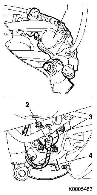
Remove brake calliper (1) complete with linings and retaining
frame, and suspend at a suitable point
Note: If the brake
calliper cannot be removed, the brake linings of the rear wheel
brake must be removed - see operation "Brake Linings - Rear Wheel
Brake, Remove and Install" in this group
|
| 3. |
Detach wheel bearing unit (3) with brake cover plate (4) and
brake disc from steering knuckle
|
| 4. |
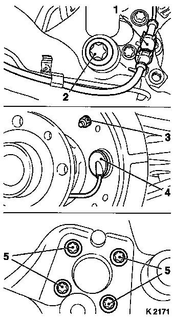
Release ABS wiring harness plug (2) at wheel bearing unit and
disconnect
|
| 5. |
Remove brake cover plate from wheel bearing unit
|
|
|
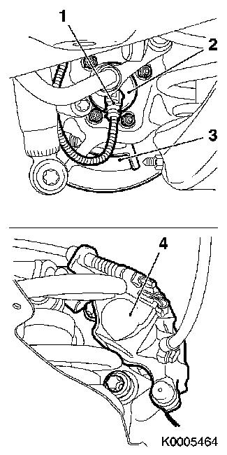
| 6. |
Disconnect wiring harness plug for wheel sensor (1) and unclip
from rear brake hose.
|
| 7. |
Detach rubber grommet (4) from wheel sensor wiring harness on
brake disc cover plate
| • |
Thread wiring harness for wheel sensor through cover plate to
wheel bearing unit
|
| • |
Detach fastening nut for brake hose bracket (3) from cover
plate
|
|
| 8. |
Support rear axle with a hydraulic jack on the side to be
fitted
|
| 9. |
Detach fastening bolt (2) for shock absorber on trailing
link
|
| 10. |
Detach fastening bolts for wheel bearing unit on trailing link
(5)
| • |
Remove wheel bearing unit with cover plate
|
|
|
|
| 11. |
Clean contact surfaces of wheel bearing unit, cover plate at
trailing link.
|
 Install
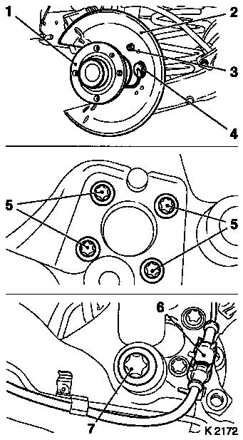
| 12. |
Attach wheel bearing unit (1) with brake plate (2) to trailing
link with new fastening bolts (5) - tightening torque 50 Nm + 30° + 15°
|
| 13. |
Thread wiring harness for wheel sensor (4) through cover
plate
| • |
Clip wheel sensor wiring harness (4) on to brake hose
Note: Ensure the rubber
grommet is seated correctly on the brake disc cover plate.
|
|
| 14. |
Attach bracket for brake hose (3) to cover plate - tightening
torque 8 Nm .
|
| 15. |
Attach shock absorber with fastening bolt (7) to trailing link
- tightening torque 110 Nm
|
| 16. |
Connect wheel sensor wiring harness plug (6) electrically
|
| 17. |
Remove hydraulic jack
|
|
|
| 18. |
Plug ABS wiring harness plug (1) into wheel bearing unit
|
| 19. |
Attach retaining frame for brake calliper with brake calliper
(4) to steering knuckle
|
| 20. |
Detach retaining frame for brake calliper from wheel housing
with brake calliper
|
| 21. |
Coat 2x new bolts with locking compound
|
| 22. |
Screw in 2x new bolts ( 130 Nm
)
|
| 24. |
Screw in 5x bolts ( 110 Nm )
Note: Observe
installation position.
|
|
|
|
