|
Exhaust Gas Recirculation Valve, Z10XEP,
Z14XEP
Objective:
Checking the electrical and mechanical functions of the Exhaust
Gas Recirculation Valve.
Measurement:
Plot of voltage at the control input of the exhaust gas
recirculation valve as well as the voltage of the feedback
signal.
Preparation:
Switch off the engine and ignition.
Connections:
|
INPUT A
|
COM/TRIGGER
|
INPUT B
|
|
Connect the red measurement lead to pin 1 of the plug connector
of the exhaust gas recirculation valve. Connect the black ground
lead to ground.
|
|
Connect the grey measurement lead to pin 4 of the plug connector
of the exhaust gas recirculation valve.
|
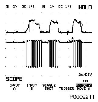
The exhaust gas recirculation valve is only being actuated under
certain circumstances (load, engine speed, etc.). The Reference
curve shows the correlation between the signal of the valve and the
feedback signal while driving the car.
Note: For several
engine management systems it is possible to activate the EGR valve
with an actuator test in the Tech 2.
Procedure Tech 31:
| 1. |
Download Reference curve. |
| 2. |
For this test it is necessary to drive the
vehicle. |
| 3. |
Start the engine and drive the vehicle slowly in
first gear (Automatic Transmission in 1). |
| 4. |
Alternate the engine speed between 1500 and 2500
revs/min in partial load to allow the Exhaust Gas Recirculation
valve to be actuated. |
|
Reference Curve:
|
|
Procedure Tech 32:
| 1. |
Download Setup file (the Tech 32 uses only Setup
files, no reference curves). |
| 2. |
For this test it is necessary to drive the
vehicle. |
| 3. |
Start the engine and drive the vehicle slowly in
first gear (Automatic Transmission in 1). |
| 4. |
Alternate the engine speed between 1500 and 2500
revs/min in partial load to allow the Exhaust Gas Recirculation
valve to be actuated. |
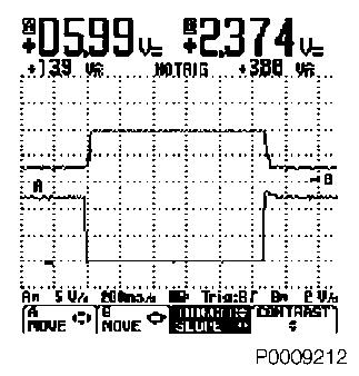
Setup File:
|
Reference Curve:
|
|
|
