|
Measuring crankshaft
Note: Dismantle
engine
 Install
| 1. |
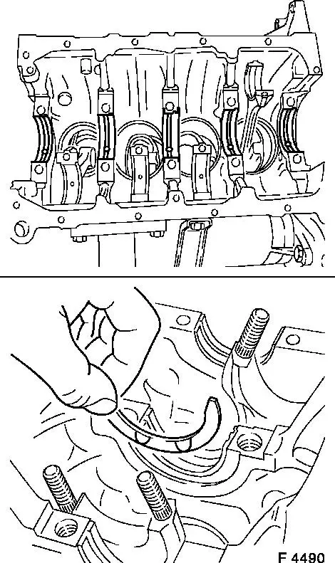
Insert 10 crankshaft bearing shells
| • |
Observe installation position and allocations
|
| • |
Note position of axial bearing
|
| • |
In cylinder block, crankshaft bearing cap
|
|
| 2. |
Insert crankshaft
| • |
Insert 2 thrust rings
Note: Oil grooves face
outward
|
|
|
|
| 3. |
Attach 5 crankshaft bearing covers
| • |
Pay attention to identification, allocation and tightening
order. Arrows point toward engine control side.
|
| • |
Tighten 10 bolts
Note: Bolts do not have
to be replaced when checking crankshaft alignment
| – |
Tightening torque 88.2 Nm
|
|
|
|
|
| 4. |
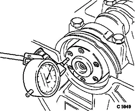
Attach MKM-571-B
| • |
Install MKM-571-B in bracket
|
| • |
Fit bracket to transmission side of cylinder block
|
|
|
|
 Measure
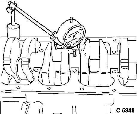
| 5. |
Adjust MKM-571-B
| • |
Attach probe to crankshaft flange
|
| • |
Attach MKM-571-B under
pre-tension
|
|
| 6. |
Measure crankshaft end play
| • |
Read off test value
Note: Repeat
measurement several times. For permitted crankshaft end play see
"Technical Data - crank drive, cylinder block"
|
|
| 8. |
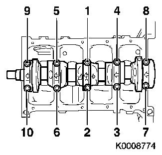
Remove 5 crankshaft bearing covers
| • |
Slacken in depicted order
|
|
|
|
| 9. |
Attach MKM-571-B
| • |
Attach to cylinder block with bracket
|
|
|
|
| 10. |
Adjust MKM-571-B
| • |
Place probe against crankshaft bearing journal
|
| • |
Attach MKM-571-B under
pre-tension
|
|
| 11. |
Measure crankshaft concentricity deviation
| • |
Read off test value
Note: For permitted
crankshaft concentricity deviation see "Technical Data - Crank
Drive, Cylinder Block"
|
|
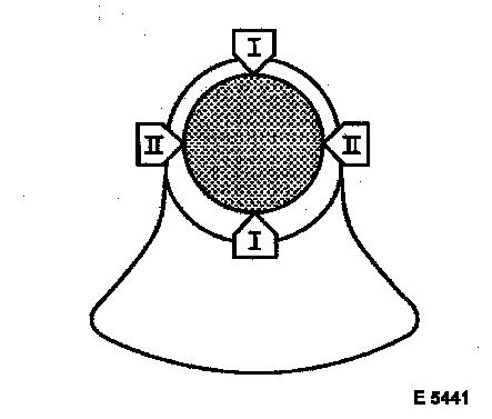
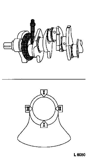
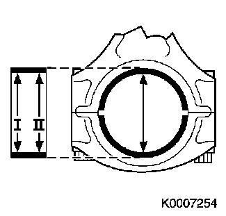
| 14. |
Measure diameter of 5 crankshaft bearing journals
| • |
Measure in 2 places (I + II) per bearing using micrometer
gauge
Note: Note dimensions -
if a dimension is outside the permitted tolerance, the crankshaft
must be ground or replaced.
|
|
|
|
| 15. |
Attach 5 crankshaft bearing covers
| • |
Pay attention to identification and allocation. Arrows point to
engine control side
|
| • |
Tighten 10 bolts
Note: Bolts do not have
to be replaced when checking crankshaft alignment
| – |
Tightening torque 88.2 Nm
|
|
|
|
|
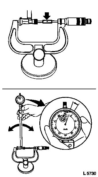
| 16. |
Set up internal measuring instrument
| • |
Fit appropriate probe tip to internal measuring instrument
| – |
Fit MKM-571-B to internal measuring
instrument with approx. 1 mm of pre-tension
|
|
| • |
Slide internal measuring instrument between micrometer gauge
test surfaces
|
| • |
Determine indicator turning point
| – |
Oscillate internal measuring instrument between test
surfaces
|
| – |
Set MKM-571-B to "0" at turning
point
|
|
|
|
|
| 17. |
Measure diameter of 10 crankshaft bearing holes
| • |
Determine turning point 2 places (I + II) per bearing
| – |
Oscillate internal measuring instrument in crankshaft bearing
hole
|
|
| • |
Note down the dimensions
|
|
|
|
| 18. |
Calculate crankshaft bearing play (5 times)
Note: The crankshaft
bearing play is calculated on the basis of the difference between
the crankshaft bearing bore and crankshaft bearing journal
diameters. For permitted crankshaft bearing play see "Technical
Data - crank drive, cylinder block"
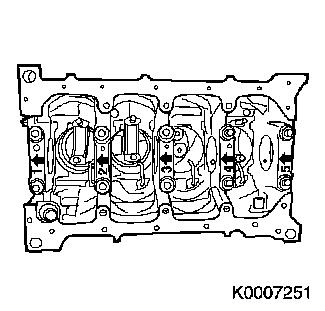
| • |
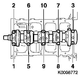
When selecting main bearing shells the following must be taken
into consideration:
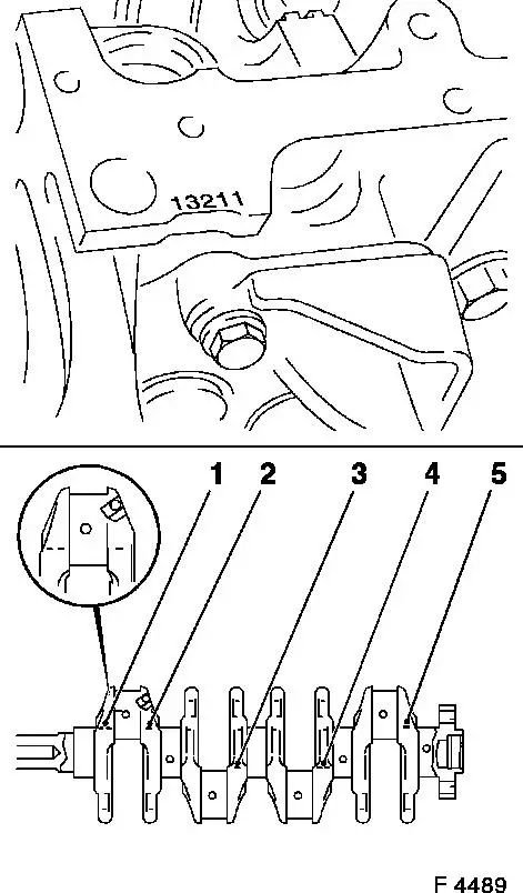
The main bearing shells are divided into three classes. The class
depends on the bore diameter for the main bearing shells in the
cylinder block and is identified by a number per main bearing shell
in the cylinder block, see F4489 above.
The inner diameter of the main bearing shells depends on the outer
diameter of the main bearing journals. Depending on the diameter,
the crankshaft cheeks are marked with "-" or "- -". The numbers (1
to 5) relate to the respective main bearing journals. The (1)
relates to the left-hand main bearing journals shown at the bottom
of figure F4489, and the others relate to the right-hand main
bearing journals. Bearing shells with appropriate play can be
selected using these identifiers - see "Technical Data".
|
|
|
|
| 19. |
Remove 5 crankshaft bearing covers
|
| 20. |
Remove 10 crankshaft bearing shells
|
| 21. |
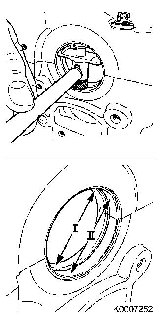
Measure diameter of 4 con-rod journals
| • |
Measure in 2 places (I, II) using micrometer gauge
Note: Note dimensions -
if a dimension is outside the permitted tolerance, the crankshaft
must be ground or replaced.
|
|
|
|
| 22. |
Insert 8 con-rod bearing shells
| • |
Observe installation position and allocations
|
| • |
In con-rod, con-rod bearing cap
|
|
| 23. |
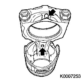
Attach 4 con-rod bearing caps
| • |
Pay attention to identification (arrows) and allocation
|
| • |
Tighten 8 nuts
Note: Nuts do not have
to be replaced when measuring con-rod bearing play
| – |
Tightening torque 24.5 Nm + 100°+
15°
|
|
|
|
|
| 24. |
Reconfigure internal measuring instrument
| • |
Fit appropriate probe tip to internal measuring instrument
| – |
Fit MKM-571-B to internal measuring
instrument with approx. 1 mm of pre-tension
|
|
| • |
Slide internal measuring instrument between micrometer gauge
test surfaces
|
| • |
Determine indicator turning point
| – |
Oscillate internal measuring instrument between test
surfaces
|
| – |
Set MKM-571-B to "0" at turning
point
|
|
|
| 25. |
Measure diameter of 4 con-rod bearing holes
| • |
Determine turning point in 2 places (I, II)
| – |
Oscillate internal probe in con-rod bearing hole
|
|
| • |
Note down the dimensions
|
|
|
|
| 26. |
Calculate con-rod bearing play (4 times)
Note: The con-rod
bearing play is calculated on the basis of the difference between
the con-rod bearing bore and con-rod bearing journal diameters. For
permitted con-rod bearing play see "Technical Data - crank drive,
cylinder block"
|
 Remove Remove
| 27. |
Remove 4 con-rod bearing caps
|
| 28. |
Remove 8 con-rod bearing shells
|
| 29. |
Dismantle internal measuring instrument
|
|
