|
Removing and installing crankshaft (Y 17 DTL)
| 1. |
Remove engine
Note: See operation "J
4501 00 Remove and install engine".
|
| 2. |
Detach manual transmission from engine
Note: See operation "J
4501 00 007 Remove and install manual transmission from/to
engine".
|
| 3. |
Drain engine oil
| • |
Place collecting basin underneath.
|
|
| 4. |
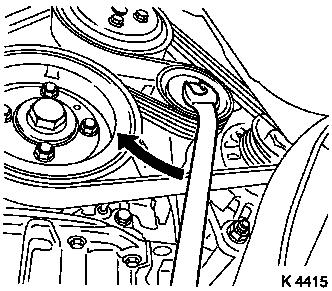
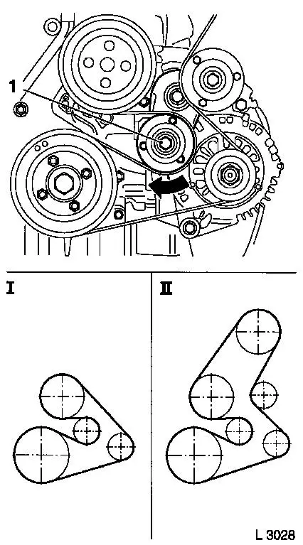
Remove ribbed V-belt
| • |
Tension ribbed V-belt tensioner in direction of arrow
Note: Mark direction of
rotation
|
|
|
|
| 5. |
Remove oil dipstick guide tube
|
| 6. |
Detach upper toothed belt cover
| • |
Remove 8 bolts
Note: Note dissimilar
bolt lengths
|
|
|
|
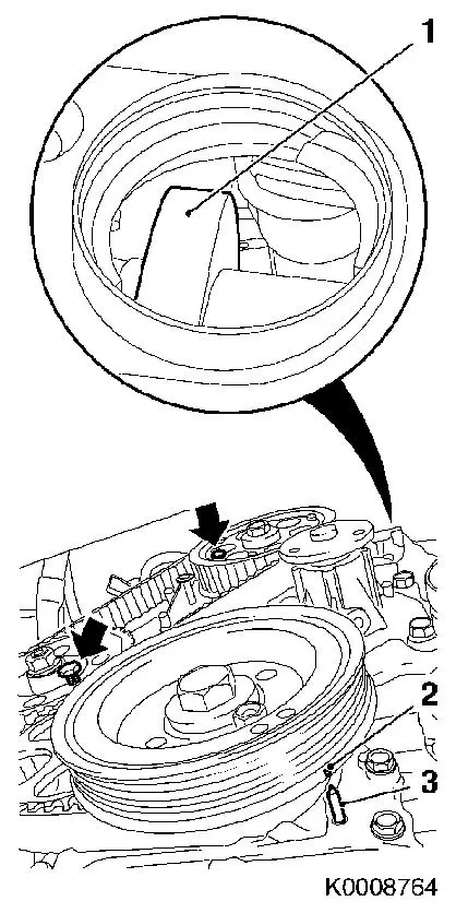
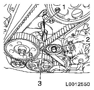
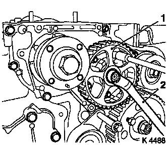
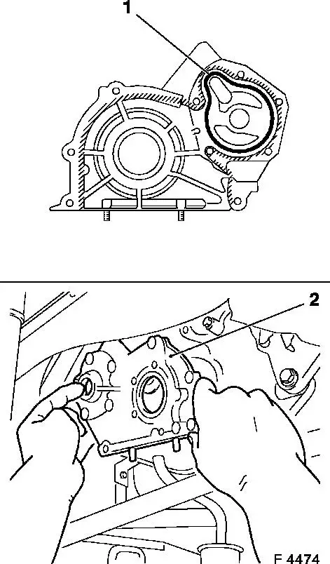
| 7. |
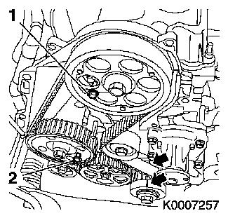
Set no.1 cylinder to TDC
| • |
Rotate crankshaft evenly until torsional vibration damper mark
(2) is flush with pin (3) on oil pump cover. Pair of no.1 cylinder
exhaust cams (1) must be on top.
|
| • |
Screw in the TDC fixing bolts (arrows)
| – |
Drive gear injection pumps (M8)
|
|
|
|
|
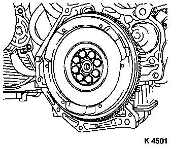
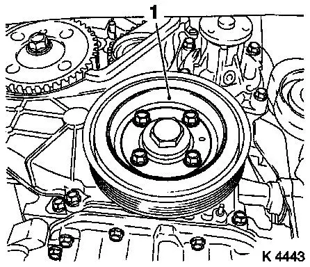
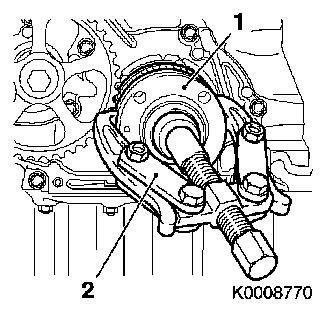
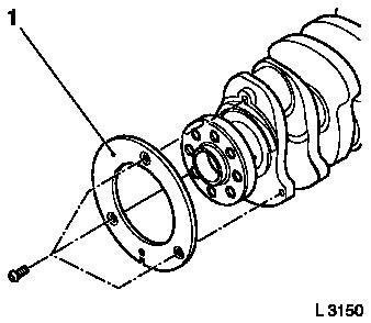
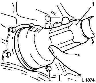
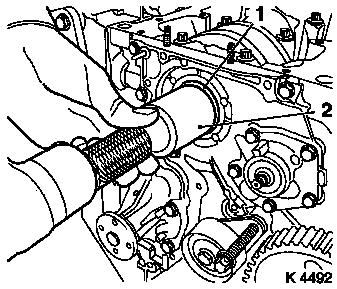
| 8. |
Remove torsional vibration damper (1)
|
| 9. |
Detach coolant pump ribbed V-belt pulley
|
|
|
| 10. |
Detach lower part of toothed belt cover
|
|
|
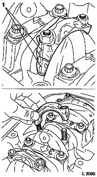
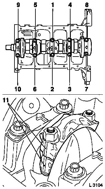
| 11. |
Detach right engine bracket
|
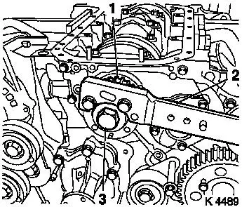
| 12. |
For toothed belt tension roller with leaf spring:
| • |
loosen toothed belt tensioner
| – |
Screw in bolt (M10) in lower bore (3) of toothed belt
tensioner
|
| – |
Remove tension spring (1)
|
|
|
|
|
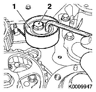
| 13. |
For toothed belt tension roller with spiral spring:
| • |
Loosen toothed belt tension roller (1)
| – |
Rotate toothed belt tension roller anticlockwise approx.
90°
|
|
|
|
|
| 14. |
Remove oil pump drive gear (1)
| • |
Unscrew nut (2)
Note: Counterhold using
socket wrench and unscrew nut using spanner (2).
|
|
|
|
| 15. |
Remove toothed belt drive gear bolt (3)
| • |
Counterhold toothed belt drive gear (1) using KM-662-C (2)
Note: 2nd mechanic
|
|
|
|
| 16. |
Remove toothed belt drive gear (1)
|
| 17. |
Remove clutch
Note: Remove clutch -
see operation "Remove and install thrust plate and clutch disc
(without SAC)" in group "K".
|
|
|
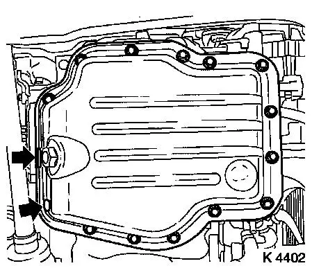
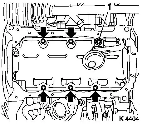
| 20. |
Detach oil pan lower part
| • |
Remove using KM-J-37228
|
|
|
|
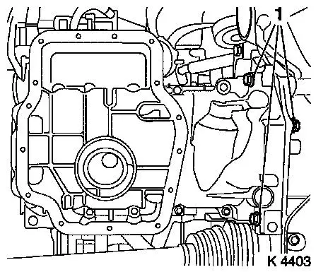
| 21. |
Detach oil pan upper part
Note: Bolts (1) have
been unscrewed.
| • |
Remove 14 bolts
Note: Note dissimilar
bolt lengths
|
| • |
Remove 2 nuts
Note: Use wide
spatula.
|
|
|
|
| 22. |
Remove oil intake pipe
|
|
|
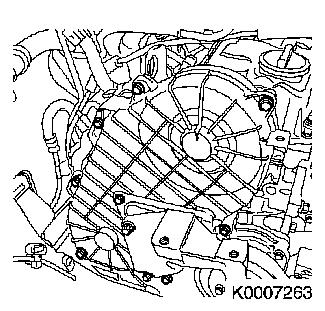
| 23. |
Remove oil baffle plate
| • |
Remove 5 bolts (arrows)
|
|
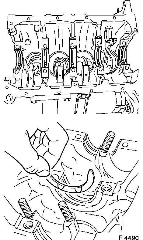
| 24. |
Remove con-rod bearing caps
| • |
Remove con-rod bearing shells
Note: Pay attention to
identifier on con-rod bearing cover and con-rod (1). If not
present, mark with identifier.
|
|
| 25. |
Remove con-rod bearing shells
| • |
Mark con-rod bearing shells
Note: Follow order.
|
|
|
|
| 26. |
Remove oil pump cover (1)
| • |
Remove 9 bolts
Note: Note dissimilar
bolt lengths
|
| • |
Remove inner and outer rotors
|
|
|
|
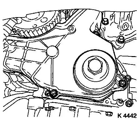
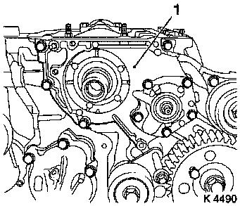
| 27. |
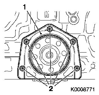
Remove rear crankshaft cover sealing ring (1)
Important: Note guide bushings
when removing.
|
| • |
Carefully prise off rear crankshaft sealing ring cover
|
|
|
|
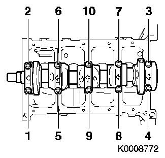
| 28. |
Remove crankshaft
| • |
Remove crankshaft bearing cover
Note: Undo crankshaft
bearing cover fastening screws in depicted order (1 - 10).
| – |
Remove 10 bolts
Note: Place crankshaft
onto wooden blocks.
|
|
|
|
|
| 29. |
Remove crankshaft bearing shells
| • |
Mark crankshaft bearing shells
Note: Note markings on
crankshaft bearing shells.
|
|
|
|
| 31. |
Remove crankshaft pulse pick-up (1)
|
|
|
| 32. |
Clean components
| • |
Oil pan lower section, oil pan upper section, cylinder
block
|
|
| 34. |
Install crankshaft pulse pick-up
| • |
Tighten bolts ( 10.8 Nm )
|
|
| 35. |
Insert con-rod bearing shells
| • |
In con-rod, con-rod bearing cap
|
|
Important: Pay attention to
identification and allocation
|
| 36. |
Insert crankshaft bearing shells
| • |
In cylinder block and crankshaft bearing cover
|
|
| 37. |
Replace thrust rings
| • |
Oil grooves face outward
|
|
|
|
| 38. |
Insert crankshaft
| • |
Coat crankshaft journals with engine oil
Note: Note installation
position.
|
|
| 39. |
Fit crankshaft bearing cover
Important: Note installation
position. Arrows point to engine control side.
|
| • |
Renew bolts
|
| • |
Tighten bolts ( 88.2 Nm )
Note: Note tightening
order (1 - 10).
|
|
|
|
| 40. |
Attach con-rod bearing cap
Important: Note cylinder order
markings on con-rod bearing cover and con-rod (11). Narrow bead
faces engine control side.
|
| • |
Replace nuts
|
| • |
Tighten nuts ( 24.5 Nm + 100° +
15° )
|
|
| 41. |
Remove rear crankshaft sealing ring
Important: Do not damage sealing
surface.
|
| • |
Lever out seal ring
|
|
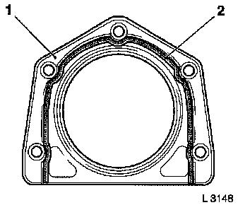
| 42. |
Fit rear crankshaft sealing ring cover (1)
Note: Ensure correct
seating of guide bushings.
| • |
Apply adhesive sealing compound (black) (2)
Note: Use screw locking
compound (red)
|
| • |
Tighten bolts ( 9.8 Nm )
Note: Fit screws within
10 minutes.
|
|
|
|
| 43. |
Fit rear crankshaft sealing ring
| • |
Coat sealing lip with grease
|
| • |
Attach KM-658-2 to crankshaft
journal
|
| • |
Slide sealing ring onto KM-658-2
|
| • |
Drive in until flush using KM-658-1
(1)
|
|
|
|
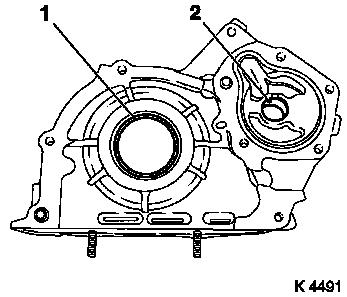
| 44. |
Remove oil pump cover sealing rings
| • |
Front crankshaft sealing ring (1), oil pump sealing ring
(2)
Important: Do not damage sealing
surface.
|
| – |
Prise out sealing rings
|
|
|
|
|
| 45. |
Attach oil pump
| • |
Insert inner and outer rotor
|
| • |
Apply adhesive sealing compound (black)
|
| • |
Attach oil pump cover (2)
| – |
Note different bolt lengths
|
| – |
Tighten bolts ( 9.8 Nm )
|
|
|
|
|
| 46. |
Install oil pump cover sealing rings
| • |
Coat sealing lips with silicon grease (white)
|
| • |
Install oil pump seal ring
| – |
Drive in until flush using KM-657
|
|
| • |
Install front crankshaft sealing ring (1)
| – |
Drive in until flush using KM-656
(2)
|
|
|
|
|
| 47. |
Install oil baffle plate
| • |
Tighten bolts ( 18.6 Nm )
|
|
| 48. |
Install oil intake pipe
| • |
Tighten bolt ( 18.6 Nm )
|
|
| 50. |
Attach oil pan upper section
| • |
Apply silicon sealing compound (grey)
|
| • |
Tighten bolts, nuts ( 9.8 Nm
)
|
|
| 51. |
Attach oil pan lower section
| • |
Apply silicon sealing compound (grey)
|
| • |
Tighten bolts ( 9.8 Nm )
|
|
| 52. |
Screw in oil drain screw
|
| 54. |
Attach flywheel
| • |
Tighten bolts ( 29,4 Nm + 45° +
15° )
Note: Use screw locking
compound (red)
|
|
| 55. |
Install clutch
Note: Remove clutch -
see operation "Remove and install thrust plate and clutch disc
(without SAC)" in group "K".
|
| 57. |
Install toothed belt drive gear
| • |
Install sheet metal panel
|
| • |
Insert toothed belt drive gear in place
|
|
| 58. |
Tighten toothed belt drive gear
| • |
Counterhold using KM-662-C
Note: 2nd mechanic
|
| • |
Tighten bolt ( 196 Nm )
|
|
| 59. |
Install oil pump drive gear
Note: Pay attention to
installation position
| • |
Tighten nut ( 44.1 Nm )
|
|
| 60. |
Install toothed belt
| • |
Set no.1 cylinder to TDC
| – |
Mark on toothed belt drive gear must align with lug on oil pump
cover (arrows)
|
|
|
|
|
| 61. |
Install toothed belt
| • |
Position toothed belt
Note: Toothed belt must
be taut from toothed belt drive gear via oil pump drive gear and
injection pump drive gear
|
| • |
For toothed belt tension roller with leaf spring:
|
| • |
Unscrew TDC-fixing bolt
|
| • |
Rotate crankshaft 60° against direction of engine
rotation
|
| • |
Tighten bolt of toothed belt tension roller
| – |
For toothed belt tension roller with spiral spring 49 Nm
|
| – |
For toothed belt tension roller with leaf spring 38.2 Nm
|
|
| • |
For toothed belt tension roller with leaf spring: unscrew bolt
(M10) from lower bore of toothed belt tensioner
|
|
| 62. |
Timing, Check
| • |
Turn crankshaft approx. 780° in direction of engine
rotation
|
| • |
Mark on toothed belt drive gear must align with casting lug at
oil pump cover
|
| • |
Install TDC-fixing bolt
Note: If the TDC fixing
bolts cannot be screwed in, basic adjustment must be repeated
|
| • |
Unscrew TDC-fixing bolts
|
|
| 63. |
Attach right engine bracket
| • |
Screw in bolt with bushing
|
|
| 64. |
Attach lower part of toothed belt cover
| • |
Tighten bolts ( 9.8 Nm )
|
|
| 65. |
Attach upper toothed belt cover
| • |
Tighten bolts ( 9.8 Nm )
Note: Note dissimilar
bolt lengths
|
|
| 66. |
Attach coolant pump ribbed V-belt pulley
| • |
Tighten bolts ( 9.8 Nm )
|
|
| 67. |
Install torsional vibration damper
| • |
Tighten bolts ( 19.6 Nm )
|
|
| 68. |
Install oil dipstick guide tube
| • |
Tighten bolt ( 9.8 Nm )
|
|
| 69. |
Install ribbed V-belt
| • |
Tension ribbed V-belt tensioner in direction of arrow
Note: Observe running
direction
|
|
|
|
| 70. |
Attach transmission
Note: See operation "J
4501 00 007 Remove and install manual transmission from/to
engine".
|
| 71. |
Install engine
Note: See operation
"Remove and install engine".
|
| 72. |
Pour in engine oil
| • |
Start engine and allow to run until oil pressure telltale
extinguishes.
|
| • |
Check engine oil level, if necessary correct.
|
| • |
Use prescribed quantity of oil
|
|
|