|
J 452700 All Pistons with Con-rods, Remove and
Install (Y 17 DT, with AC, LHD)
Note: KM-6394 must be used from model year 04 instead of
KM-6169-1 .
|
1. Open bonnet
2. Drain air conditioning
- Note! Drain air conditioning – see operation "Drain air
conditioning" in group "D"
Caution!
On vehicles from model year 04 with ESP - the steering angle
sensor loses its basic adjustment each time the battery is
disconnected. It must be recalibrated.
3. Disconnect battery
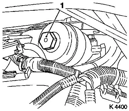
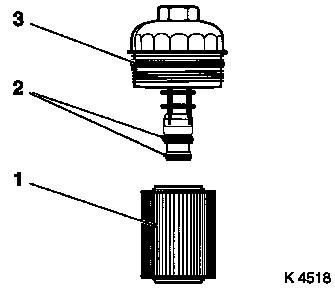
4. Remove oil filter insert
- Place collecting basin underneath.
- Unscrew oil filter housing cover (1)
|
|
|
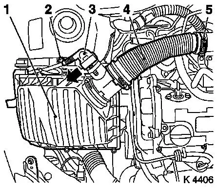
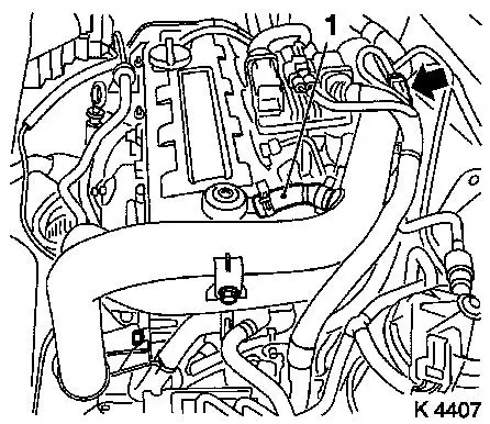
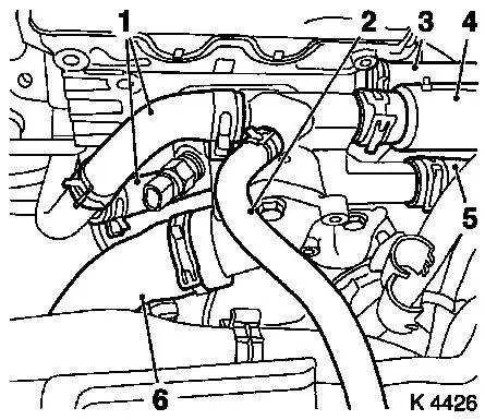
5. Remove air cleaner housing (1)
- Disconnect wiring harness plug for hot film mass air flow meter
(3)
- Release in direction of arrow
- Remove air intake hose (4)
- Remove bolt (2)
|
|
6. Detach refrigerant line
- From compressor
- Remove bolt
7. Remove oil dipstick guide tube
- Unscrew upper bolt
- Unclip vacuum lines
8. Loosen right front wheel.
9. Raise vehicle
|
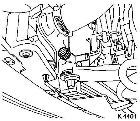
10. Drain coolant
- Place collecting basin underneath.
- Open coolant expansion tank cover
- Open drain bolt
|
|
11. Remove right front wheel.
12. Raise vehicle
13. Close coolant drain bolt
|
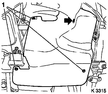
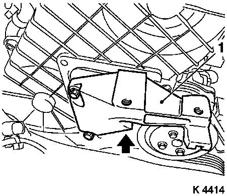
14. Remove ribbed V-belt cover
- Remove 3 bolts (1)
- Remove clip (arrow).
|
|
15. Drain engine oil
- Place collecting basin underneath.
- Remove drain bolt
16. Install drain bolt
- Replace seal ring
- Tighten bolt (78.4 Nm / 57.9 lbf. ft.)
17. Loosen front exhaust pipe
Note: When removing
the centre muffler, a catalytic converter, an exhaust manifold, or
an exhaust manifold with catalytic converter, secure that portion
of the exhaust system remaining on the vehicle against uncontrolled
suspension.
For this purpose, the exhaust system portion including the flexpipe
may be fastened to the vehicle underbody using suitable means, e.g.
wire.
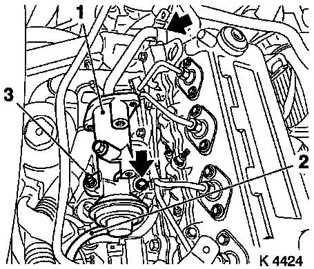
Caution!
Angular dislocations of the flexpipe as small as 5 to 10 degrees
offset from the intended installation position can already cause
damage and subsequent complete failure of the flexpipe.
18. Detach exhaust system
- Remove from damping rings
- Note! 2. mechanic
- Hang exhaust system aside and suspend in place
19. Remove oil dipstick guide tube
|
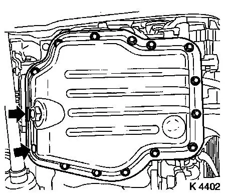
20. Detach oil pan lower part
- Remove 15 bolts
- Detach with KM-J-37228
|
|
|
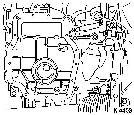
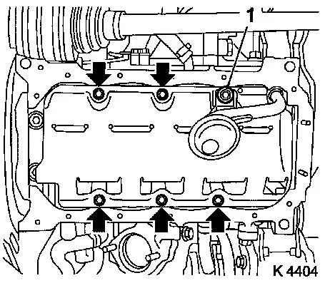
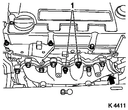
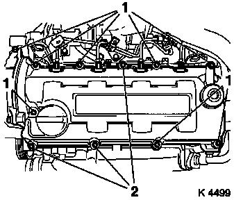
21. Detach oil pan upper part
- Remove 14 bolts
- Note! Note dissimilar bolt lengths
- Remove 3 bolts (1)
- Remove 2 nuts
- Note! Use wide spatulas
- Push oil dipstick guide tube upwards
|
|
|
22. Detach oil intake pipe
23. Remove oil baffle plate
|
|
|
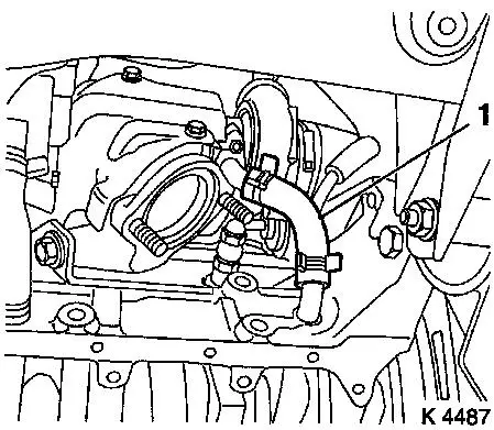
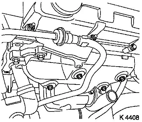
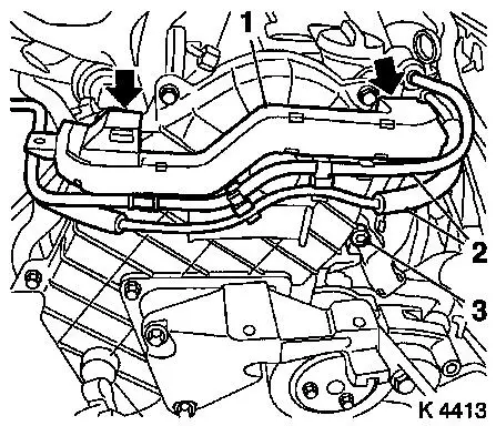
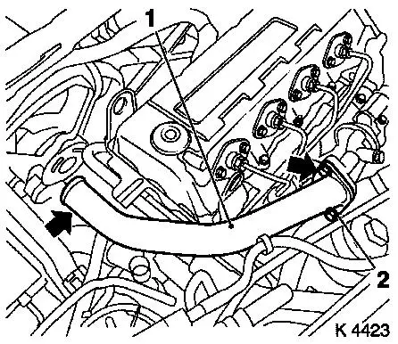
24. Detach turbocharger oil return hose
(1)
|
|
|
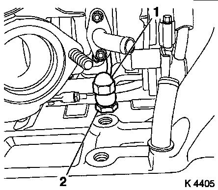
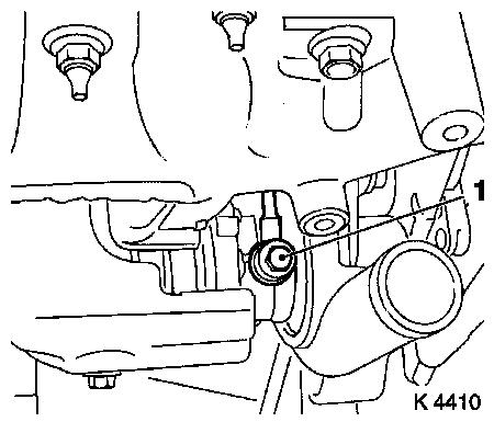
25. Remove turbocharger oil feed
line
- Unscrew nut (1)
- Note! Counterhold at threaded port (2)
|
|
26. Release turbocharger bracket
27. Detach waste gate unit vacuum hose
28. Detach air intake pipe
|
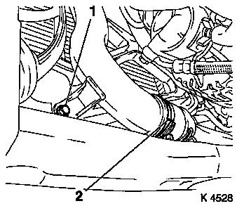
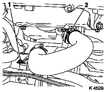
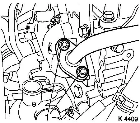
29. Detach centre charge air pipe
- from lower charge air pipe
- Remove lower bolt (1)
- Loosen clamp (2)
|
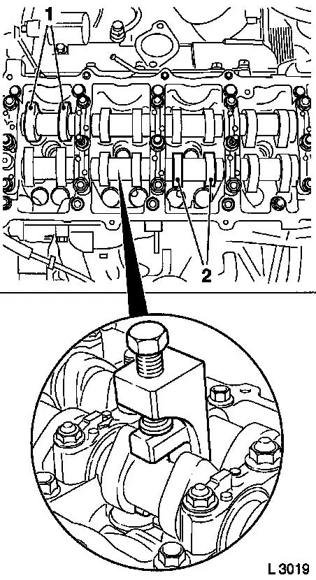
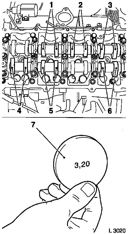
|
|
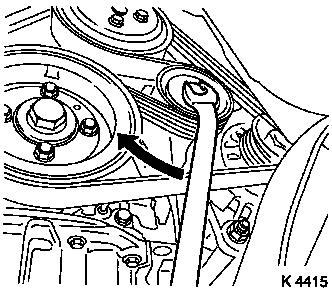
30. Remove ribbed V-belt
- Tension ribbed V-belt tensioner in direction of arrow
- Note! Mark running direction
|
|
|
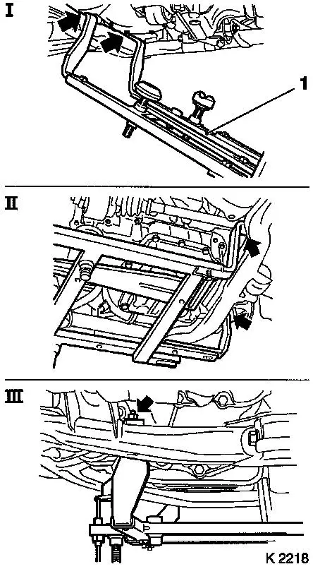
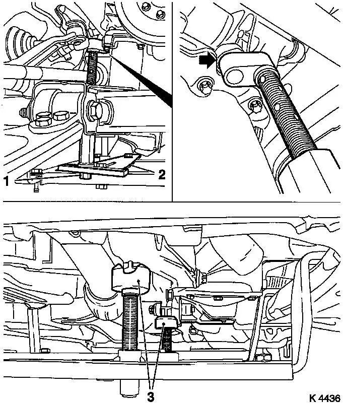
31. Attach KM-6169 (1)
- Place left of KM-6169 onto front axle body (arrows, illus.
I)
- Note! Guide pin must be seated in bore in front axle body
- Attach both right holders on the front axle body (arrows,
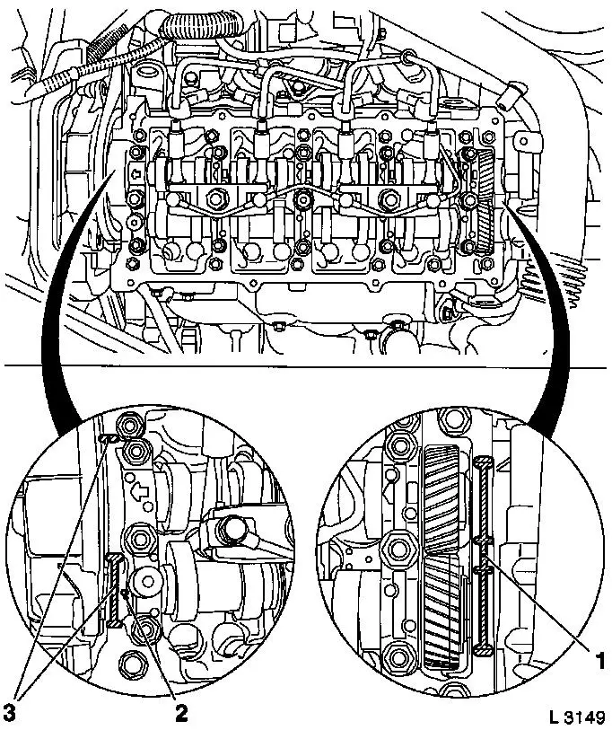
Illus. II).
- Note! Guide pin must be seated in bore in front axle body
(arrow, Illus. III)
- Tighten bolts
|
|
|
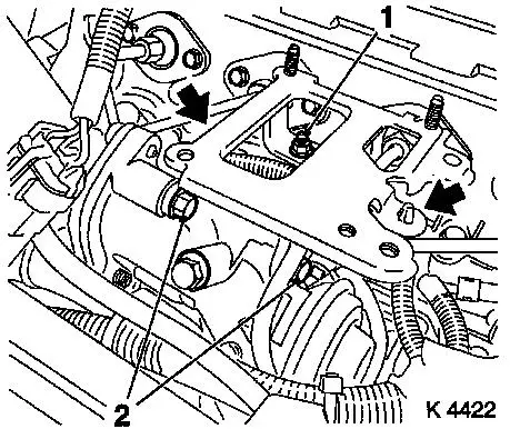
32. Install support
- To KM-6169
- Adjust bracket (2) for support
- Screw on nut (1)
33. Adjust supports
- Transmission side
- Note! Turn spindles until the mounts (3) are positioned at the
guide journals free of play
- Engine timing side
- Insert journal of the support in the bore of the cylinder block
without play (arrow)
- Tighten nuts (1)
|
|
34. Lower vehicle
35. Remove compressor
- Remove wiring harness plug
- Remove 3 bolts
- Note! Note dissimilar bolt lengths
36. Detach oil dipstick guide tube bracket
- From camshaft housing cover
- Unclip vacuum hoses
37. Remove oil dipstick guide tube
38. Remove compressor bracket
|
39. Detach centre charge air pipe
- Remove upper bolt (1)
- Detach charge air hose from turbocharger
|
|
|
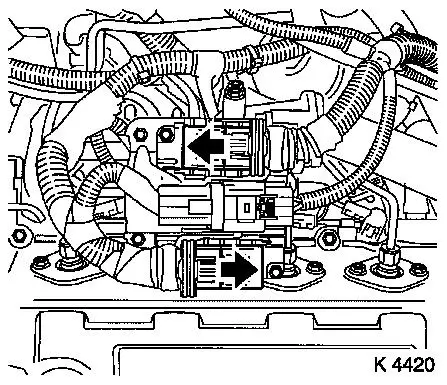
40. Remove wiring harness plug for
engine management
- Detach 2 engine control unit wiring harness plugs
- Release in direction of arrow
- Disconnect combination plug (grey)
- Disconnect combination plug (black)
|
|
|
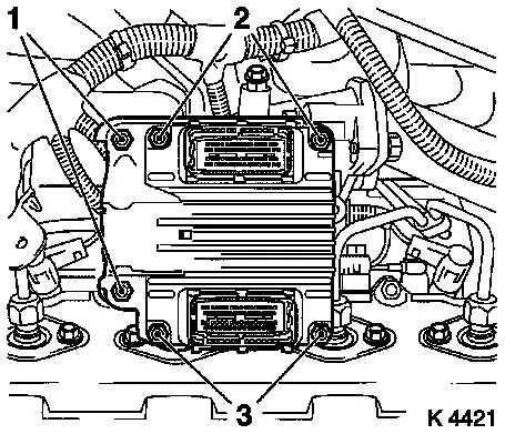
41. Remove engine control unit
- Remove wiring harness plug bracket
- Unscrew 2 bolts (2), 2 nuts (3)
|
|
|
42. Detach air intake pipe
- Remove 2 bolts
- Detach engine vent hose (1)
- Detach air intake pipe from turbocharger
- Unclip wiring harness
|
|
|
43. Unclip brake servo vacuum line
44. Detach exhaust manifold heat
shield
|
|
|
45. Remove exhaust gas recirculation
pipe
|
|
|
46. Remove turbocharger oil feed
line
- Unscrew banjo bolt (1)
- Remove seal rings
|
|
|
47. Remove exhaust manifold
- Remove 7 bolts
- Remove 2 nuts (1)
- Remove gasket.
|
|
|
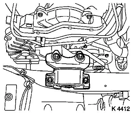
48. Remove right engine damping
block
|
|
|
49. Detach alternator wiring
harness
- Disconnect wiring harness plug (1)
- Unscrew nut (2)
- Unclip wiring harness
|
|
|
50. Detach wiring trough (1)
- Unclip vacuum lines (2)
- Unclip wiring trough
- Remove bolt (3)
|
|
|
51. Detach right engine bracket (1)
|
|
|
52. Release upper toothed belt
cover
- Remove 8 bolts
- Note! Note dissimilar bolt lengths
- Remove adapter for right engine bracket
|
|
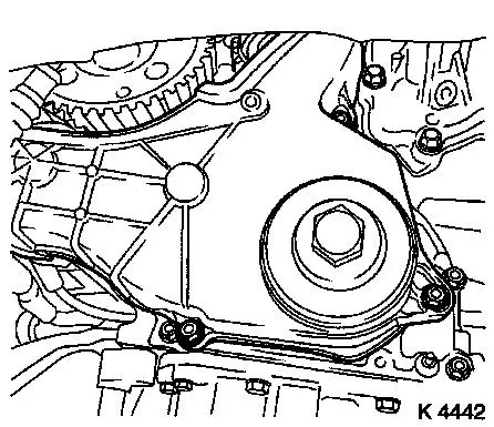
53. Detach coolant pump ribbed V-belt
pulley
|
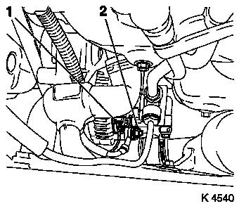
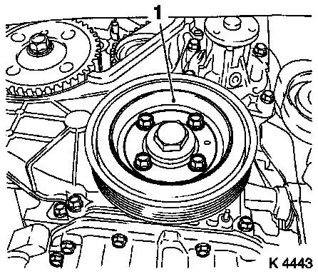
54. Remove torsional vibration damper
(1)
|
|
|
55. Remove lower toothed belt cover
|
|
|
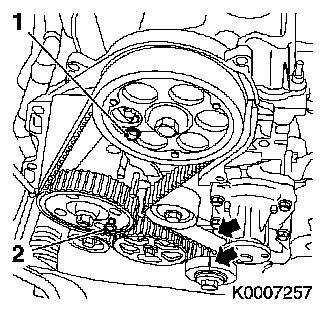
56. Set 1st cylinder to TDC
- Turn crankshaft evenly until TDC-fixing bolts can be
inserted
- Camshaft gear (M6) (1)
- Injection pump gear (M8) (2)
- Note! The mark on toothed belt drive gear must align with lug
on oil pump cover (arrows)
|
|
|
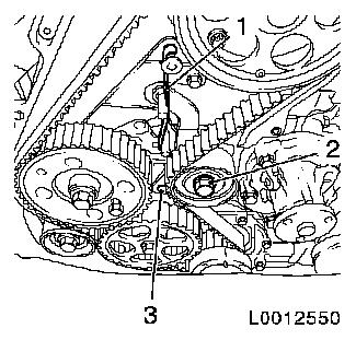
57. For toothed belt tension roller
with leaf spring:
- loosen toothed belt tensioner
- Screw in bolt (M10) in lower bore (3) of toothed belt
tensioner
- Loosen bolt (2)
- Remove tension spring (1)
|
|
|
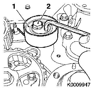
For toothed belt tension roller with
spiral spring:
- Loosen toothed belt tension roller (1)
- Rotate toothed belt tension roller anticlockwise approx.
90°
- Tighten bolt (2)
|
|
58. Remove toothed belt
- Note! Mark running direction
|
59. Detach camshaft pulley
- Unscrew TDC-fixing bolt (2)
- Counterhold camshaft gear using KM-6156 and KM-956-1
- Remove bolt (1)
|
|
60. Loosen toothed belt tension roller spring retainer
61. Release rear toothed belt cover
|
62. Remove engine control unit
bracket
- Unscrew 2 bolts (2), nut (1)
- Unclip wiring harness (arrows)
|
|
|
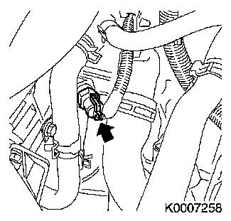
63. Remove wiring harness for engine
management
- Disconnect wiring harness plug
- Coolant temperature sensor (arrow), oil pressure switch, diesel
injection pump (3), sheathed glow plugs
- Unclip wiring harness
- Set wiring harness to one side
|
|
|
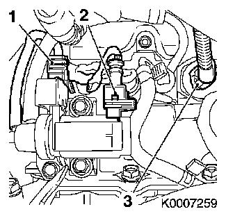
64. Disconnect wiring harness plug
- Exhaust gas recirculation solenoid valve (2), charge pressure
sensor (1)
|
|
|
65. Remove upper charge air pipe (1)
- Remove charge air hose
- Unscrew stud (2), 2 bolts (arrows)
66. Detach starter/alternator wiring harness bracket
- From exhaust recirculation valve
- Unscrew nut
|
|
|
67. Remove exhaust gas recirculation
valve (1)
- Unscrew studs (3), 2 bolts (arrows)
- Detach vacuum hose (2)
- Remove gasket.
|
|
|
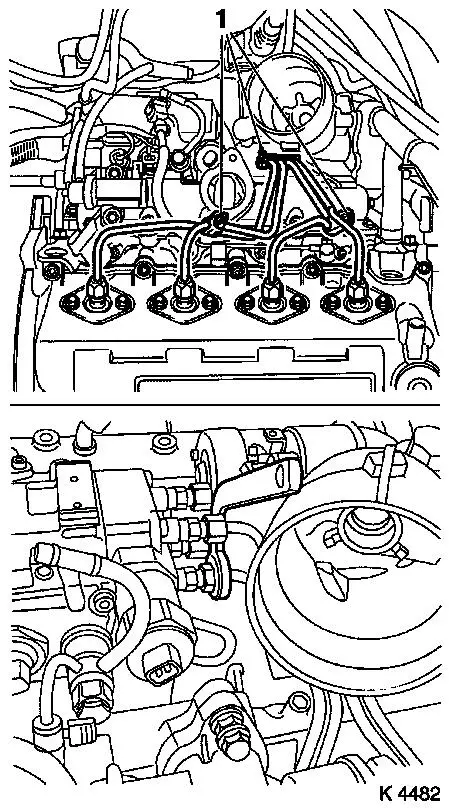
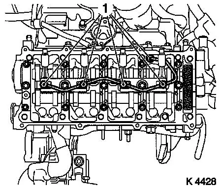
68. Detach injection line spacers (1)
69. Remove injection lines
|
|
70. Detach vacuum hose
- From exhaust gas recirculation solenoid valve
71. Detach oil leak line
|
72. Detach coolant hoses
- From thermostat
- Upper radiator hose (6), coolant pipe 2 off (1), coolant
compensation tank (2), add-on heater (5), heater core (4)
- From cylinder head (3)
|
|
|
73. Detach waste gate unit vacuum hose bracket
74. Remove engine transport shackles
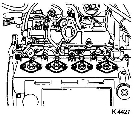
75. Detach injection nozzle outer seals
|
|
|
76. Remove camshaft housing cover
- Unscrew 7 bolts (1), 3 stud bolts (2)
|
|
|
77. Detach inner oil leak line
- Unscrew 5 banjo bolts (1)
- Note! Note sealing rings
|
|
|
78. Remove injector nozzles
Caution!
Ensure that upon removal of injector nozzles heat protection
sleeves remain in their position on the cylinder head.
Otherwise, heat protection sleeves must
be removed completely and installed again using new seal rings.
This is the only way to ensure that no coolant can reach the
combustion chamber, which would inevitably cause engine damage.
Replace heat protection sleeves – see operation "Replace heat
protection sleeves" in document "Check and measure cylinder
head".
- Remove injection nozzle bracket
- Remove injector nozzles
|
|
|
79. Remove camshaft housing cover
- Loosen bolts, stud bolts (180°)
- Caution! Observe sequence
- Unscrew 2 stud bolts, 15 bolts
- Remove gasket.
|
|
|
80. Remove cup tappets
- With KM-845
- Caution! Observe installation position and allocation
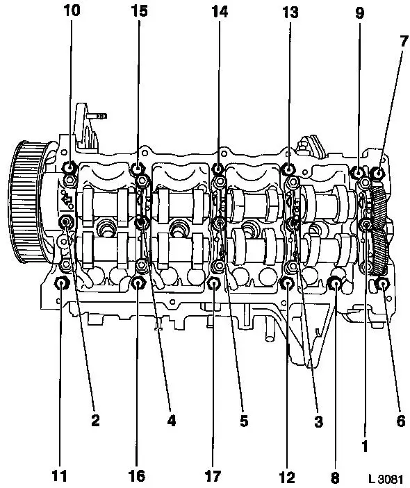
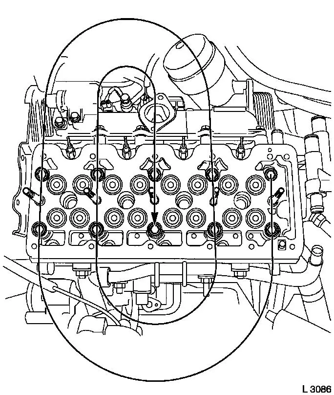
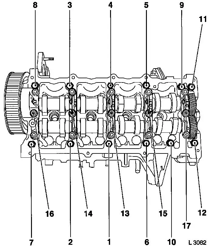
81. Remove cylinder head bolts
- Remove 10 bolts
- Note! Loosen bolts in order shown (180° –
360°)
|
|
82. Remove cylinder head
- Note! 2. mechanic
- Caution! Place cylinder head on wooden blocks, note sheathed
glow plugs
- Remove cylinder head gasket
83. Raise vehicle
|
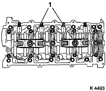
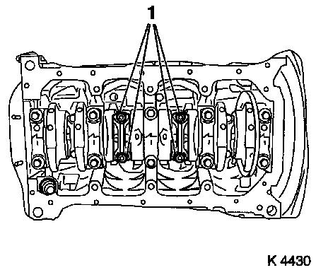
84. Remove con-rod bearing caps
- 2. and 3rd cylinder
- Remove con-rod bearing caps
- Note! Observe identification on con-rod bearing caps and
con-rods. If not present, apply identification
- Push piston upwards
|
|
85. Turn crankshaft
- In direction of engine rotation by 180°
|
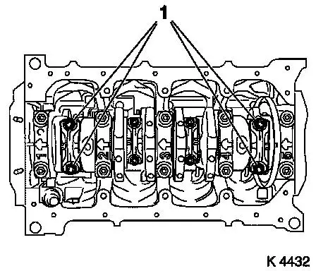
86. Remove con-rod bearing caps
- 1. and 4th cylinders
- Remove con-rod bearing caps
- Note! Observe identification on con-rod bearing caps and
con-rods. If not present, apply identification
- Push piston upwards
|
|
87. Lower vehicle
88. Remove piston
- 4 off
- Remove combustion residues
89. Remove con-rod bearing shells
- From con-rod, con-rod bearing cap
90. Visually inspect components
- Crankshaft with con-rod and piston assemblies, engine timing
components, cylinder head, cylinder block, exhaust manifold,
turbocharger, valve train, ribbed V-belt drive
91. Install con-rod bearing shells
|
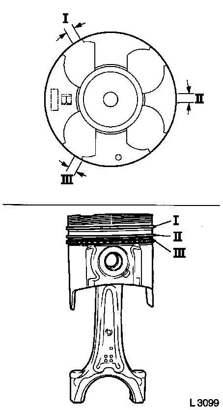
92. Adjust piston rings
- Arrange piston ring end gaps offset by 120°
- I Rectangular ring (first compression ring)
- II Tapered ring (second compression ring)
- III Double-bevelled ring (oil scraper ring)
|
|
|
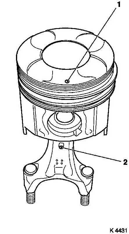
93. Install piston
- 1. and 4th cylinders
- Caution! Mark (1) on piston head and mark (2) on con-rod point
to engine timing side
- Compress piston rings with piston ring tensioner
- Insert piston
|
|
94. Raise vehicle
|
95. Attach con-rod bearing cap
- Replace nuts
- Caution! Observe identification of cylinder sequence on con-rod
bearing caps and con-rods. Small bead (arrow) points towards engine
timing side
- Tighten nuts (24.5 Nm / 18.1 lbf. ft. + 100° +
15°)
|
|
96. Turn crankshaft
- In direction of engine rotation by 180°
97. Lower vehicle
|
98. Install piston
- 2. and 3rd cylinder
- Caution! Mark (1) on piston head and mark (2) on con-rod point
to engine timing side
- Compress piston rings with piston ring tensioner
- Insert piston
|
|
99. Raise vehicle
|
100. Attach con-rod bearing cap
- Replace nuts
- Caution! Observe identification of cylinder sequence on con-rod
bearing caps and con-rods. Small bead (arrow) points towards engine
timing side
- Tighten nuts (24.5 Nm / 18.1 lbf. ft. + 100° +
15°)
|
|
101. Lower vehicle
102. Clean sealing surfaces
- Cylinder head, cylinder block, camshaft housing, camshaft
housing cover, exhaust manifold, turbocharger, exhaust gas
recirculation valve, upper charge air pipe
|
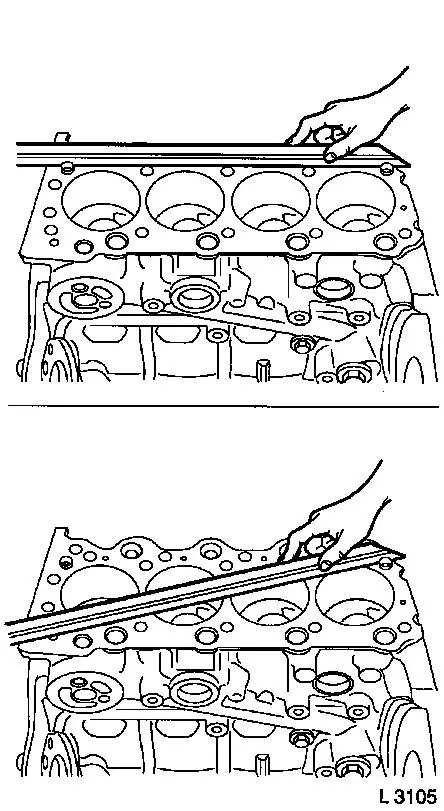
103. Check for plane surface
- Cylinder head, cylinder block
- With straightedge, feeler gauge
|
|
|
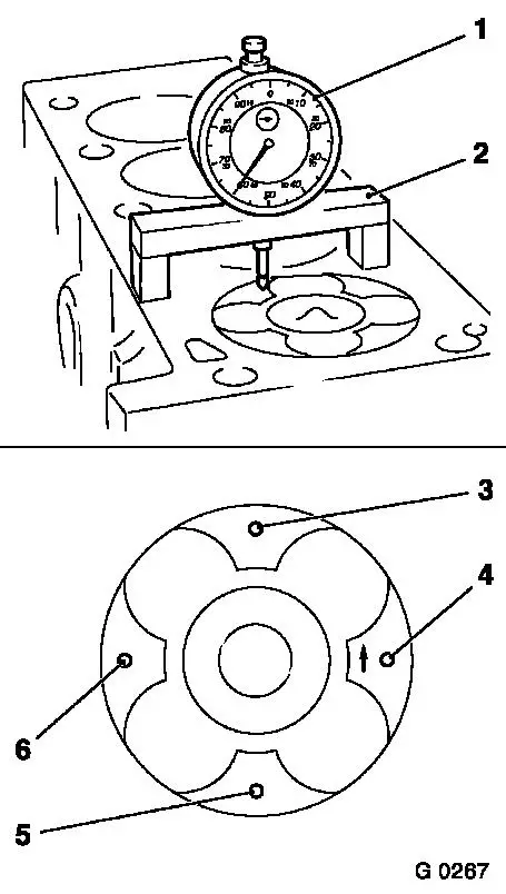
104. Measure piston projection
- Insert MKM-571-B (1) in KM-301 (2)
- Set dial to zero
- Place probe on cylinder block
- Measure piston projection on all four pistons
- Carry out measurement on two different locations (3 and 4) or
(5 and 6)
- Determine high point by turning crankshaft
|
|
105. Turn crankshaft
- approx. 60° before TDC of cylinder-1
|
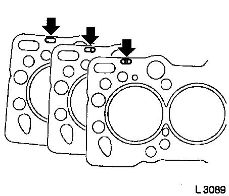
106. Replace cylinder head gasket
|
Piston projection
|
Thickness of cylinder head gasket
|
Code
|
|
0.630 – 0.696 mm
|
1.45 mm
|
no hole
|
|
0.697 – 0.763 mm
|
1.50 mm
|
one hole
|
|
0.764 – 0.830 mm
|
1.55 mm
|
two holes
|
- Caution! The largest determined piston projection is used for
the selection of the cylinder head gasket with corresponding
identification (arrows).
- Lay cylinder head gasket in place
|
|
107. Position cylinder head
|
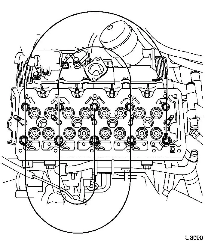
108. Fasten cylinder head
- Replace cylinder head bolts
- Screw in bolts by several threads
- Tighten cylinder head bolts (39.2 Nm + 60° + 13° +
60° + 13°)
- Note! Observe tightening sequence
|
|
109. Insert cup tappets
- Coat with engine oil
- Caution! Observe sequence and allocation
|
110. Install camshaft housing
- Replace gasket
- Tighten bolts M8 (21.6 Nm / 16 lbf. ft.)
- Tighten bolts M10 (43.1 Nm / 32 lbf. ft.)
- Caution! Observe sequence
|
|
111. Fasten rear toothed belt cover
- Tighten bolts (9.8 Nm / 7.2 lbf. ft.)
112. Attach camshaft gear
- Counterhold using KM-6156 and KM-956-1
- Tighten bolt (63.7 Nm / 47.0 lbf. ft.)
- Install TDC-fixing bolt
113. For toothed belt tension roller
with leaf spring: fasten toothed belt tension roller spring
retainer
|
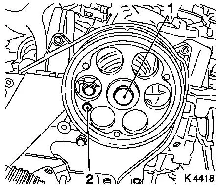
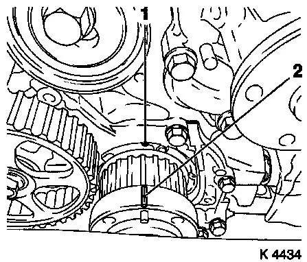
114. Set cylinder 1 to TDC
- Mark on toothed belt drive gear (2) must align with casting lug
at oil pump cover (1)
|
|
115. Install toothed belt
Note: Toothed belt
must be taut from toothed belt drive gear via oil pump drive gear
and injection pump drive gear
- For toothed belt tension roller with leaf spring:
- Unscrew TDC-fixing bolt
- Rotate crankshaft 60° against direction of engine
rotation
- Tighten bolt of toothed belt tension roller
- For toothed belt tension roller with spiral spring 49 Nm
- For toothed belt tension roller with leaf spring 38.2 Nm
116. For toothed belt tension roller with leaf spring: unscrew
bolt (M10) from lower bore of toothed belt tensioner
|
117. Check timing
- Turn crankshaft approx. 780° in direction of engine
rotation
- At toothed belt drive gear bolt
- The mark on toothed belt drive gear must align with lug on oil
pump cover (arrows)
- Install TDC-fixing bolt
- Camshaft gear M6 (1)
- Injection pump drive gear M8 (2)
- Note! If the TDC fixing bolts cannot be inserted, the basic
adjustment must be repeated
|
|
118. Unscrew TDC-fixing bolts
|
119. Turn crankshaft
- Turn crankshaft until cam pairs (1) and (2) point upwards
|
|
120. Check valve play
- Using feeler gauge
- Test values: Intake valves/Exhaust valves (0.35 – 0.45
mm)
- Note! Checking and adjustment of valve clearances is done on a
cold engine – room temperature
121. Adjust valve play
- Turn cup tappet until tappet groove points outwards
- Press down cup tappets using KM-6090
- Note! Note different tool versions for intake and exhaust
valves
- Mark – IN = Intake side
- Mark – EX = Exhaust side
- Caution! Ensure that valves do not interfere with piston
head
- Remove adjustment shim
Example for determination of shim
thickness
|
1.
|
Thickness of installed shim
|
|
3.15 mm
|
|
2.
|
Measurement between cam and cup tappets
|
+
|
0.45 mm
|
|
|
|
=
|
3.60 mm
|
|
3.
|
Nominal valve play
|
-
|
0.40 mm
|
|
4.
|
Thickness of new shim
|
=
|
3.20 mm
|
|
122. Insert shim
- Coat new shim with engine oil and insert in cup tappet with
identification mark facing downwards
123. Turn crankshaft
- In direction of engine rotation by 180°
- Check and adjust valve pair (6) and (2)
- In direction of engine rotation by 180°
- Check and adjust valve pair (5) and (3)
- In direction of engine rotation by 180°
- Check and adjust valve pair (4) and (1)
- Note! Valve clearances must be checked again for all adjusted
valves
|
|
124. Install lower toothed belt
cover
- Tighten bolts (9.8 Nm / 7.2 lbf. ft.)
125. Install torsional vibration
damper
- Tighten bolts (19.6 Nm / 14.5 lbf. ft.)
126. Attach right engine bracket
- Insert lower bolt
- Into right engine bracket and right engine bracket adapter
- Insert right engine bracket, right engine bracket adapter,
upper part of toothed belt cover
- Install 2 upper bolts
- Tighten 3 bolts (40 Nm / 29.5 lbf. ft.)
127. Fasten upper toothed belt
cover
- Tighten bolts (9.8 Nm / 7.2 lbf. ft.)
- Note! Note dissimilar bolt lengths
128. Attach coolant pump ribbed V-belt
pulley
- Tighten bolts (9.8 Nm / 7.2 lbf. ft)
129. Install right engine damping
block
- To side member
- Tighten bolts (40 Nm / 29.5 lbf. ft.)
- On engine bracket
- Tighten bolts (60 Nm/44 lbf. ft + 30° + 15°.)
130. Install injector nozzles
- Renew seal rings
- Renew copper sealing washers
- Insert injection nozzles in cylinder head.
- Install injector nozzle bracket (22.1 Nm/16.3 lbf. ft.)
131. Attach new inner oil leak line
- Renew seal rings
- Tighten banjo bolt (14.7 Nm/10.8 lbf. ft.)
|
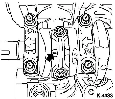
132. Attach camshaft housing cover
- Replace gasket
- Apply adhesive sealant compound (white)
- Caution! Oil return bore (2) must not be covered with adhesive
sealing compound or by the camshaft housing cover gasket
- Tighten bolts, studs (9.8 Nm/7.2 lbf. ft.)
|
|
133. Attach injection nozzle outer
seals
- Replace seals
- Tighten bolts
134. Install injection lines
- Caution! Injection lines must be installed without tension.
Hand-tighten at injector nozzles and injection pump.
- With KM-6098
- Tighten union nuts (22.5 Nm/16.6 lbf. ft.)
135. Install injection line spacers
- Note! Note spacer positions
|
136. Install oil filter element (1)
- Replace seal rings (2)
- Replace oil filter housing cover (3)
- Install new oil filter element into cover
- Tighten oil filter housing cover (25 Nm/18.5 lbf. ft.)
|
|
137. Attach waste gate unit vacuum hose
bracket
- Tighten bolt (24.5 Nm / 18.1 lbf. ft.)
138. Attach coolant hoses
139. Attach engine transport
shackles
- 3 off
- Tighten bolts (20 Nm / 15 lbf. ft.)
140. Attach oil leak hose
141. Connect wiring harness plug
- Exhaust gas recirculation solenoid valve, charge pressure
sensork
142. Attach vacuum hose
- To exhaust gas recirculation solenoid valve
143. Install exhaust gas recirculation
valve
- Replace gasket
- Tighten studs, bolts (24.5 Nm/18.1 lbf. ft.)
- Connect vacuum hose.
144. Attach upper charge air pipe
- Clean sealing surface
- Replace gasket
- Tighten stud bolt, bolt
- Upper charge air pipe bracket to camshaft housing
- Tighten bolt (24.5 Nm / 18.1 lbf. ft.)
145. Attach starter/alternator wiring
harness bracket
146. Install alternator wiring
harness
- Tighten nuts
- Connect wiring harness plug.
- Attach wiring trough
- Clip-in wiring trough
- Tighten bolt
147. Attach wiring harness for engine
management
- Route wiring harness
- Connect wiring harness plug.
148. Install engine control unit
bracket
- Tighten bolts (9.8 Nm / 7.2 lbf. ft.)
- Tighten nut (9.8 Nm/7.2 lbf. ft.)
- Attach wiring harness
149. Install exhaust manifold
- Install exhaust manifold
- Replace gasket
- Screw in bolts
- Attach exhaust gas recirculation pipe
- Replace gasket
- Screw in bolts
- Tighten bolts, nuts (23.5 Nm/17.3 lbf. ft.)
- Tighten exhaust gas recirculation pipe (28.4 Nm/20.9 lbf.
ft.)
- Exhaust gas recirculation pipe bracket to camshaft housing
- Tighten bolt (8.8 Nm / 6.5 lbf. ft.)
150. Attach turbocharger oil feed
line
- Renew seal rings
- Insert oil feed line
- Tighten banjo bolt (9.8 Nm / 7.2 lbf. ft.)
151. Attach exhaust manifold heat
shield
- Tighten bolts (11.7 Nm / 8.6 lbf. ft.)
152. Raise vehicle
153. Detach support
154. Detach KM-6169
155. Attach turbocharger oil feed
line
- Renew seal rings
- Note! Counterhold at threaded port
- Tighten nut (9.8 Nm/7.2 lbf. ft.)
156. Install turbocharger oil return hose
157. Attach turbocharger bracket
- Tighten bolt (26.5 Nm / 19.6 lbf. ft.)
158. Connect waste gate unit vacuum hose
159. Clean sealing surfaces
- Cylinder block, upper part of oil pan, lower part of oil
pan
160. Install oil baffle plate
- Tighten bolts (18.6 Nm / 13.7 lbf. ft.)
161. Install oil intake pipe
- Replace seal ring
- Tighten bolt (18.6 Nm / 13.7 lbf. ft.)
162. Attach oil pan upper part
- Apply sealing compound (grey)
- Caution! The application of silicone sealing compound (grey)
and installation of lower part of oil pan including torque test
must be performed within 10 minutes!
- Tighten bolts, nuts (9.8 Nm/7.2 lbf. ft.)
- Tighten bolts (M10) (40 Nm / 29.5 lbf. ft.)
- Replace oil dipstick guide tube sealing ring
163. Attach oil pan lower part
- Apply sealing compound (grey)
- Tighten bolts (9.8 Nm / 7.2 lbf. ft.)
164. Attach exhaust system
- Note! 2. mechanic
- Install damping rings
165. Attach front exhaust pipe
- Replace gasket, nuts
- Tighten nuts (65 Nm / 48 lbf. ft.)
166. Lower vehicle
167. Install compressor bracket
- Tighten bolts (43 Nm / 31.7 lbf. ft.)
168. Install oil dipstick guide tube
169. Install compressor
- Tighten bolts (22 Nm / 16.2 lbf. ft)
- Connect wiring harness plug.
170. Attach oil dipstick guide tube
bracket
- Tighten nuts
- Clip in vacuum lines
171. Attach refrigerant line
- Renew seal rings
- Tighten bolt (20 Nm / 15 lbf. ft.)
172. Attach charge air hose
- Tighten clamp (3.5 Nm / 2.6 lbf. ft.)
173. Attach centre charge air pipe
- Insert in lower charge air pipe
- Tighten upper bolt
- Fasten turbocharger charge air hose (3.5 Nm / 2.5 lbf.
ft.)
174. Install air intake pipe
- Tighten bolts
- Attach engine vent hose
- Tighten clamp (3.5 Nm / 2.6 lbf. ft.)
- Attach wiring harness
175. Install engine control unit
- Tighten bolts, nuts (5.9 Nm/4.4 lbf. ft.)
- Install wiring harness plug bracket
- Connect wiring harness plug.
- Attach wiring harness
176. Raise vehicle
177. Fasten oil dipstick guide tube
- Tighten lower bolts (9.8 Nm / 7.2 lbf. ft.)
178. Install ribbed V-belt
- Note! Observe running direction and installation position
- Release ribbed V-belt tensioner
179. Install ribbed V-belt cover
- Tighten bolts
- Install clip
180. Fasten centre charge air pipe
- Tighten lower bolt
- Fasten clamp (3.5 Nm / 2.6 lbf. ft.)
181. Lower vehicle
182. Mount right front wheel
183. Lower vehicle
184. Fasten right front wheel
- Tighten bolts (110 Nm / 81 lbf. ft.)
185. Fasten oil dipstick guide tube
- Tighten upper bolt
- Clip in vacuum hoses
186. Install air cleaner housing
- Tighten bolt
- Fasten air intake hose.
- Tighten clamp (3.5 Nm / 2.6 lbf. ft.)
- Connect wiring harness plug to hot film mass air flow
meter
187. Top up engine oil
- Start engine and allow to run until oil pressure telltale
extinguishes.
- Check engine oil level, if necessary correct.
- Observe specified engine oil quantity
188. Top up coolant
- Note! Top up and bleed cooling system – see operation
"Top up and bleed cooling system"
- Observe specified coolant quantity
189. Connect battery
190. Calibrate steering angle
sensor
Note: Rotate the
steering wheel one time from its right-hand to its left-hand
stop.
191. Program volatile memories
192. Charge air conditioning
- Note! Charge air conditioning – see operation "Evacuate
and charge air conditioning" in group "D".
193. Close bonnet
|
