|
J 459015 Valve Stem Seals, Replace (Y 17 DT, with
AC, LHD)
Note: KM-6394 must be used from model year 04 instead of
KM-6169-1 .
|
1. Open bonnet
Caution!
On vehicles from model year 04 with ESP - the steering angle
sensor loses its basic adjustment each time the battery is
disconnected. It must be recalibrated.
2. Disconnect battery
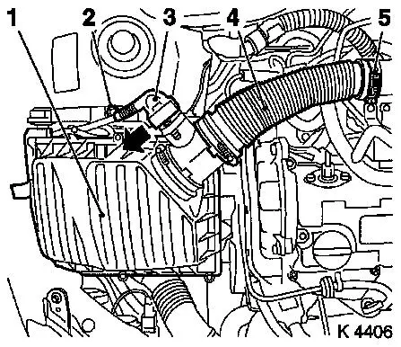
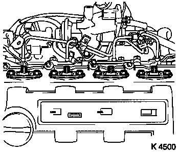
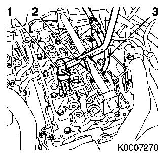
3. Remove air cleaner housing (1)
- Remove wiring harness plug for hot film mass air flow meter
(3)
- Release in direction of arrow
- Remove air intake hose (4)
- Remove bolt (2)
|
|
|
4. Loosen front right wheel
5. Raise vehicle
6. Remove front right wheel
7. Raise vehicle
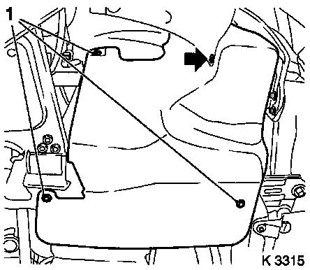
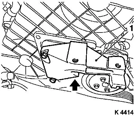
8. Detach ribbed V-belt cover
- Remove 3 bolts (1)
- Remove clip (arrow).
|
|
|
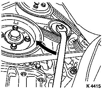
9. Detach ribbed V-belt
- Tension ribbed V-belt tensioner in direction of arrow
- Note! Mark running direction
|
|
|
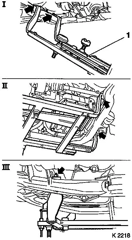
10. Release air intake pipe
11. Attach KM-6169 (1)
- Place left of KM-6169 onto front axle body (arrows, illus.
I)
- Note! Guide pin must be seated in bore in front axle body
- Attach both right holders on the front axle body (arrows,
Illus. II).
- Note! Guide pin must be seated in bore in front axle body
(arrow, Illus. III)
- Tighten bolt
|
|
|
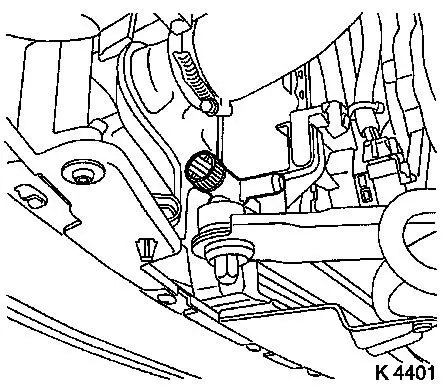
12. Install support
- To KM-6169
- Adjust bracket (2) for support
- Screw on nut (1)
13. Adjust supports
- Transmission side
- Note! Turn spindles until the mounts (3) are positioned at the
guide journals free of play
- Engine timing side
- Insert journal of the support in the bore of the cylinder block
without play (arrow)
- Tighten nuts (1)
|

|
|
14. Lower vehicle
15. Drain coolant
- Place collecting basin underneath.
- Open drain bolt
|
|
|
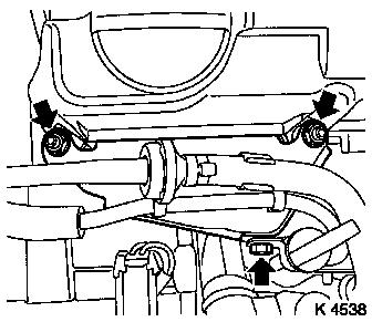
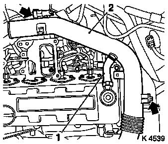
16. Remove oil dipstick guide tube
bracket
- Remove bolt, 2 nuts (arrows)
- Unclip vacuum hoses
|
|
|
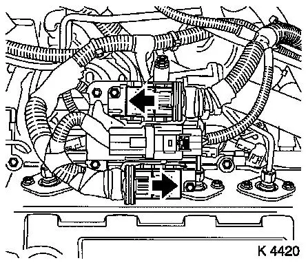
17. Remove wiring harness plug for
engine management
- Wiring harness plug, engine control unit
- Release in direction of arrow
- Disconnect combination plug (grey)
- Disconnect combination plug (black)
|
|
|
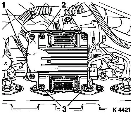
18. Remove engine control unit
- Remove wiring harness plug bracket
- Unscrew 2 bolts (2), 2 nuts (3)
|
|
|
19. Remove air intake pipe (2)
- Remove 2 bolts (arrows)
- Detach engine vent hose (1)
- Detach air intake pipe from turbocharger
|
|
|
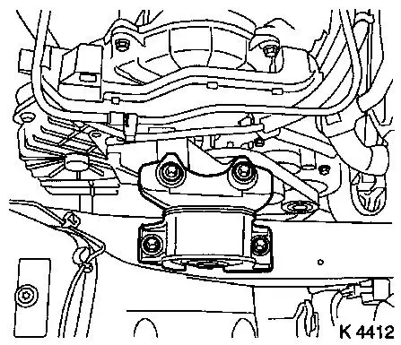
20. Remove right engine damping
block
|
|
|
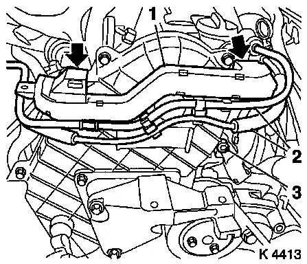
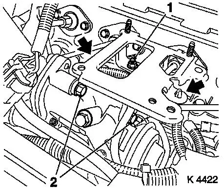
21. Remove wiring trough
- Unclip vacuum line (2)
- Unclip wiring trough (1)
- Remove bolt (3)
|
|
|
22. Remove coolant pump ribbed V-belt pulley
23. Remove upper toothed belt cover
- Remove 8 bolts
- Note! Note dissimilar bolt lengths
|
|
|
24. Detach right engine bracket (1)
- Remove 3 bolts
- Remove right engine bracket, right engine bracket adapter,
upper part of toothed belt cover
|
|
|
25. Raise vehicle
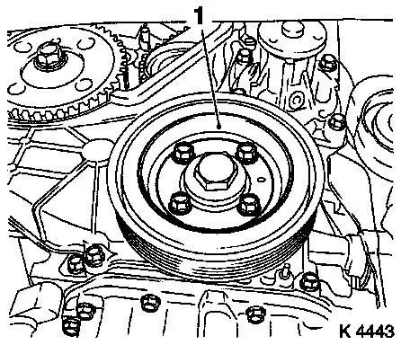
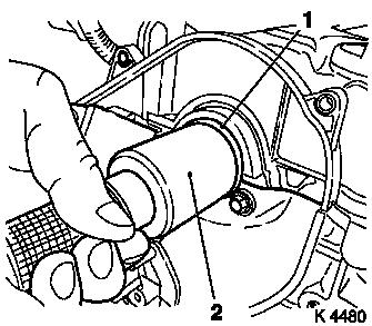
26. Remove torsional vibration damper
(1)
|
|
|
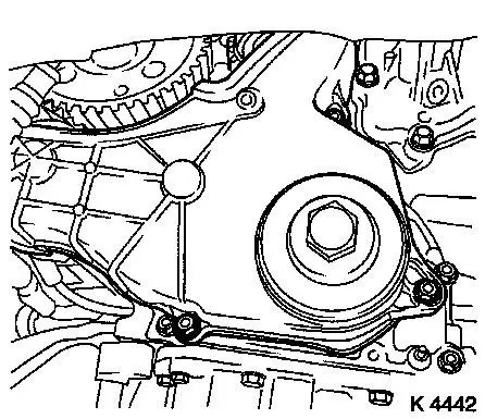
27. Remove lower toothed belt cover
|
|
|
28. Lower vehicle
29. Install right front wheel
30. Lower vehicle
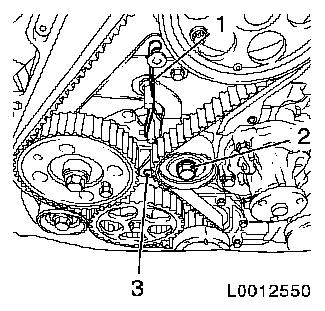
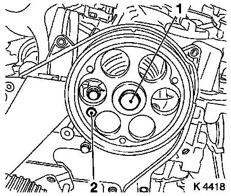
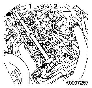
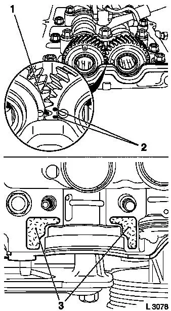
31. Set 1st cylinder to TDC of combustion stroke
- Turn crankshaft evenly until TDC-fixing bolts can be
inserted
- Camshaft gear M6 (1)
- Injection pump drive gear M8 (2)
- Note! The mark on toothed belt drive gear must align with lug
on oil pump cover (arrows)
|

|
|
32. For toothed belt tension roller
with leaf spring:
- loosen toothed belt tensioner
- Screw in bolt (M10) in lower bore (3) of toothed belt
tensioner
- Loosen bolt (2)
- Remove tension spring (1)
|
|
|
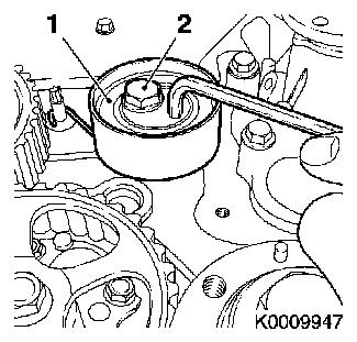
For toothed belt tension roller with
spiral spring:
- Loosen toothed belt tension roller (1)
- Rotate toothed belt tension roller anticlockwise approx.
90°
- Tighten bolt (2)
|
|
|
33. Remove toothed belt
- Note! Mark running direction
34. Detach camshaft pulley
- Unscrew TDC-fixing bolt (2)
- Counterhold using KM-6156 and KM-956-1
- Remove bolt (1)
|
|
|
35. Release rear toothed belt cover
36. Remove engine control unit bracket
- Unscrew 2 bolts (2), nut (1)
- Unclip wiring harness (arrows)
|
|
|
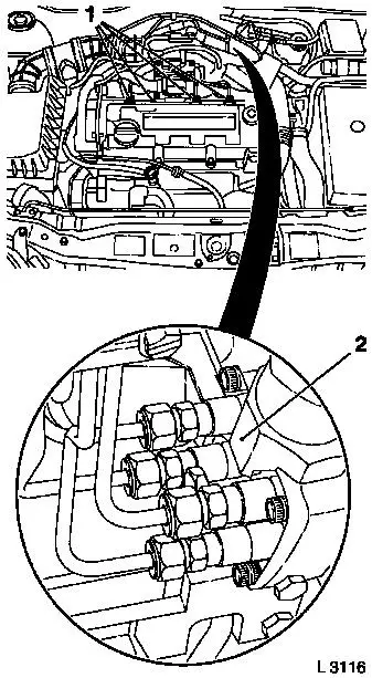
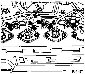
37. Detach injection line
- From camshaft housing cover (1)
- 4 off
38. Detach injection line
- From diesel injection pump (2)
- With KM-6098
- 4 off
|
|
|
39. Detach injection nozzle outer
seal
|
|
|
40. Detach right rear engine transport shackle
41. Loosen left rear engine transport shackle
42. Remove camshaft housing cover
43. Detach inner oil leak line (1)
- Remove 5 banjo bolts
- Note! Note sealing rings
|
|
|
44. Remove injector nozzles
Caution!
Ensure that upon removal of injector nozzles heat protection
sleeves remain in their position on the cylinder head.
Otherwise, heat protection sleeves must
be removed completely and installed again using sealing rings. This
is the only way to ensure that no coolant can reach the combustion
chamber, which would inevitably cause engine damage. Replace heat
protection sleeves – see operation "Replace heat protection
sleeves" in document "Check and measure cylinder head".
- Remove injection nozzle bracket
- Remove injector nozzles
|
|
|
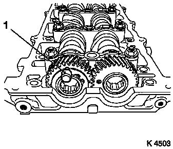
45. Lock exhaust camshaft equaliser
gear
- Insert KM-955-2 (1)
- Note! Insert in exhaust camshaft gear and exhaust camshaft
equaliser gear up to camshaft bearing cap stop. Exhaust camshaft
gear and exhaust camshaft equaliser gear must be locked in place
with rotation impossible.
|
|
|
46. Remove camshaft bearing caps
- 5 off
- Unscrew 3 bolts, 10 nuts, and 2 stud bolts
- Note! Note identification on camshaft bearing caps. The
camshafts must be uniformly released from the bearing seats. Loosen
nuts, stud bolts and bolts (180° – 360°)
|
|
|
47. Remove camshafts
- Remove intake camshaft seal ring
48. Remove cup tappets
- With KM-845
- Caution! Observe installation position and allocation
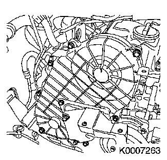
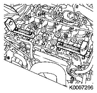
49. Remove sheathed glow plugs (arrows)
- Disconnect sheathed glow plug wiring harness plugs
- Remove sheathed glow plugs using MKM-6104.
|
|
50. Turn crankshaft
- In direction of engine rotation 90°
51. Loosen seating of valve keepers
- With KM-6171
- Loosen valve keeper seating by lightly tapping on KM-6171
52. Turn crankshaft
- In direction of engine rotation 270°
- 1st cylinder TDC of combustion stroke
53. Install stud bolts in cylinder head
|
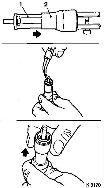
54. Assemble Automatic Valve Spring
Compressor MKM-6086
- Adjust supports
- Complete lever arm
- Using joint, removal head
- Assemble assembly head
- Insert thrust piece 6d (1)
- Note! Observe manufacturer's instructions
|
|
|
55. Attach Automatic Valve Spring
Compressor MKM-6086 supports
- To exhaust side camshaft housing cover stud bolts (1, 2 and 4,
5)
|
|
|
56. Install diesel injection nozzles
- Turn 180° offset from installation position
- 4 off
- Insert injection nozzles in cylinder head.
- Attach injection nozzle bracket
- Tighten 2 nuts (2) (22.1 Nm / 16.3 lbf. ft.)
57. Insert installation shaft and joint (1) in supports
58. Secure installation shaft
59. Fasten supports
|
|
|
60. Secure the engine against rotation
- 5. Engage gear
- Apply parking brake
- Note! Wheels must be touching the ground
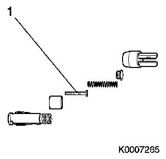
61. Install compressed air adapter (1)
- Screw into sheathed glow plug thread of 1st cylinder
- Apply compressed air to 1st cylinder
62. Attach Automatic Valve Spring Compressor MKM-6068 lever arm
(3)
- To joint (4)
- Note! Removal head (2) must face toward intake side of 1st
cylinder
|
|
|
63. Remove intake valve springs for 1st cylinder
- 2 off
- Carefully push valve springs downwards
- With lever arm
- Note! Removal head must be positioned vertically above the
valve stem
- Remove valve keepers, valve heads, valve springs
- Caution! Observe allocation
- Note! Do not use magnetic tools
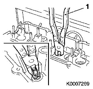
64. Replace valve stem seals
- 2 off
- Pull off using KM-840 (1)
- Attach new valve stem seal to valve stem
- Drive in using KM-6091
|
|
|
65. Remove intake valve springs for 1st
cylinder
- Insert valve springs, valve heads
- Insert valve keepers in assembly head (1)
- Slide clamping sleeve towards lever mount (arrow)
- Caution! Insert valve keepers with taper towards valve
- Slide clamping sleeve (2) towards valve (arrow)
- Attach assembly head to lever arm
- Carefully push valve springs downwards
- With lever arm
- Caution! Installation head must be positioned vertically above
the valve stem. Valve keepers must engage audibly
|
|
66. Check installation
- Caution! Do not make a 2nd attempt without checking that both
valve keepers are seated in the assembly head. Check seating of
valve keepers. Verify compressed air pressurisation
67. Transfer compressed air adapter
- Interrupt compressed air feed
- Unscrew from sheathed glow plug thread of 1st cylinder
- Screw into sheathed glow plug thread of 4th cylinder
- Apply compressed air to 4th cylinder
68. Replace 4th cylinder valve stem seals
69. Remove compressed air adapter
- Interrupt compressed air feed
- Unscrew from sheathed glow plug thread of 4th cylinder
70. Unlock engine
71. Set crankshaft to 3rd cylinder TDC of combustion stroke
- Turn crankshaft evenly (180°)
- in direction of engine rotation
72. Secure the engine against rotation
- 5. Engage gear
- Apply parking brake
- Note! Wheels must be touching the ground
73. Install compressed air adapter
- In sheathed glow plug thread
- Turn in cylinder 2
- Apply compressed air to 2nd cylinder
74. Replace 2nd cylinder valve stem seals
75. Transfer compressed air adapter
- Interrupt compressed air feed
- Unscrew from sheathed glow plug thread of 2nd cylinder
- Screw into sheathed glow plug thread of 3rd cylinder
- Apply compressed air to 3rd cylinder
76. Replace 3rd cylinder valve stem seals
77. Interrupt compressed air feed
- Note! Separate compressed air adapter from compressed air
supply
78. Detach Automatic Valve Spring Compressor MKM-6068 lever
arm
79. Release installation shaft
80. Detach installation shaft and joint from supports
81. Remove diesel injection nozzles
- Remove injection nozzle bracket
- Remove injector nozzles
82. Transfer supports
- Remove 4 nuts
- To intake side camshaft housing cover stud bolts (1, 2 and 4,
5)
- Align supports
- Secure supports
- Screw 4 nuts on stud bolts several threads
83. Install diesel injection
nozzles
- In installation position
- 4 off
- Insert injection nozzles in cylinder head.
- Attach injection nozzle bracket
- Tighten 2 nuts (22.1 Nm / 16.3 lbf. ft.)
84. Slide installation shaft and joint into supports
85. Secure installation shaft
|
86. Fasten supports
87. Attach Automatic Valve Spring Compressor MKM-6068 lever arm
(2)
- To joint
- Note! Removal head (1) must face toward exhaust side of 3rd
cylinder
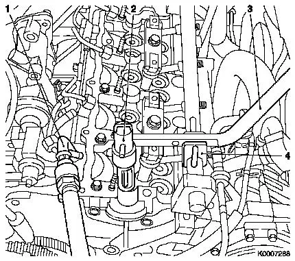
88. Install compressed air adapter (3)
- Screw into sheathed glow plug thread of 3rd cylinder
- Apply compressed air to 3rd cylinder
|
|
89. Replace 3rd cylinder valve stem seals
90. Transfer compressed air adapter
- Interrupt compressed air feed
- Unscrew from sheathed glow plug thread of 3rd cylinder
- Screw into sheathed glow plug thread of 2nd cylinder
- Apply compressed air to 2nd cylinder
91. Replace 2nd cylinder valve stem seals
92. Transfer compressed air adapter
- Interrupt compressed air feed
- Unscrew from sheathed glow plug thread of 2nd cylinder
93. Unlock engine
94. Set crankshaft to 1st cylinder TDC of combustion stroke
- Turn crankshaft evenly (180°)
- In direction of engine rotation
95. Secure the engine against rotation
- 5. Engage gear
- Apply parking brake
- Note! Wheels must be touching the ground
96. Install compressed air adapter
- Screw into sheathed glow plug thread of 1st cylinder
- Apply compressed air to 1st cylinder
97. Replace 1st cylinder valve stem seals
98. Transfer compressed air adapter
- Interrupt compressed air feed
- Unscrew from sheathed glow plug thread of 1st cylinder
- Screw into sheathed glow plug thread of 4th cylinder
- Apply compressed air to 4th cylinder
99. Replace 4th cylinder valve stem seals
100. Remove compressed air adapter
- Interrupt compressed air feed
- Unscrew from sheathed glow plug thread of 4th cylinder
101. Detach Automatic Valve Spring Compressor MKM-6068 lever
arm
102. Release installation shaft
103. Detach installation shaft and joint from supports
104. Remove diesel injection nozzles
- Remove injection nozzle bracket
- Remove injector nozzles
105. Remove supports
106. Release vehicle
107. Loosen front wheel
108. Raise vehicle
109. Remove right front wheel.
110. Lower vehicle
111. Remove stud bolts from cylinder head
112. Install sheathed glow plugs
- Install sheathed glow plugs using MKM-6104
- Tighten sheathed glow plugs (19.6 Nm / 14.4 lbf. ft.)
- Connect wiring harness plug.
113. Install cup tappets
- Coat with engine oil
- Caution! Observe sequence and allocation
114. Clean camshaft housing sealing surfaces
|
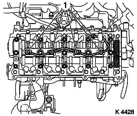
115. Insert camshafts
- Caution! Mark on exhaust camshaft gear (1) must be positioned
between both intake camshaft gear marks (2). The marks must be in
one plane with the top edge of the camshaft housing.
116. Attach camshaft bearing caps
- Note! Apply surface sealant (green) to sealing surfaces of 1st
camshaft bearing cap (3)
- 5 off
- Install nuts, stud bolts, bolts
|
|
|
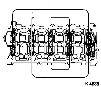
117. Tighten camshaft bearing caps
- Caution! Tighten in sequence illustrated in steps of 1/2 to 1
turn
- Tighten nuts M8 (21.6 Nm / 16 lbf. ft.)
- Tighten nuts M10 (43.1 Nm / 31.8 lbf. ft.)
- Tighten stud bolts M10 (43.1 Nm / 31.8 lbf. ft.)
- Remove KM-955-2
|
|
|
118. Install intake camshaft seal ring
(1)
- Replace seal ring
- Coat seal lips with grease
- Slide onto camshaft
- Drive in until flush using KM-656 (2)
|
|
119. Fasten rear toothed belt cover
- Tighten bolts (9.8 Nm / 7.2 lbf. ft.)
120. Attach camshaft gear
- Lock in place using KM-9156 and KM-956-1
- Tighten bolt (63.7 Nm / 47.0 lbf. ft.)
- Install TDC-fixing bolt
- Note! If the TDC fixing bolt cannot be inserted, the TDC of
combustion stroke cylinder head 1 basic adjustment must be carried
out
121. Install toothed belt
Note: Toothed belt
must be taut from toothed belt drive gear via oil pump drive gear
and injection pump drive gear
- For toothed belt tension roller with leaf spring:
- Unscrew TDC-fixing bolt
- Rotate crankshaft 60° against direction of engine
rotation
- Tighten bolt of toothed belt tension roller
- For toothed belt tension roller with spiral spring 49 Nm
- For toothed belt tension roller with leaf spring 38.2 Nm
- For toothed belt tension roller with leaf spring: unscrew bolt
(M10) from lower bore of toothed belt tensioner
|
122. Check timing
- Turn crankshaft approx. 780° in direction of engine
rotation
- At toothed belt drive gear bolt
- Note! The mark on toothed belt drive gear must align with lug
on oil pump cover (arrows)
- Install TDC-fixing bolt
- Camshaft gear M6 (1)
- Injection pump drive gear M8 (2)
- Note! If the TDC fixing bolts cannot be inserted, the basic
adjustment must be repeated
|
|
123. Unscrew TDC-fixing bolts
|
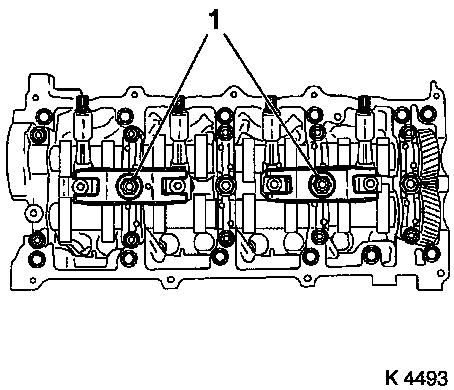
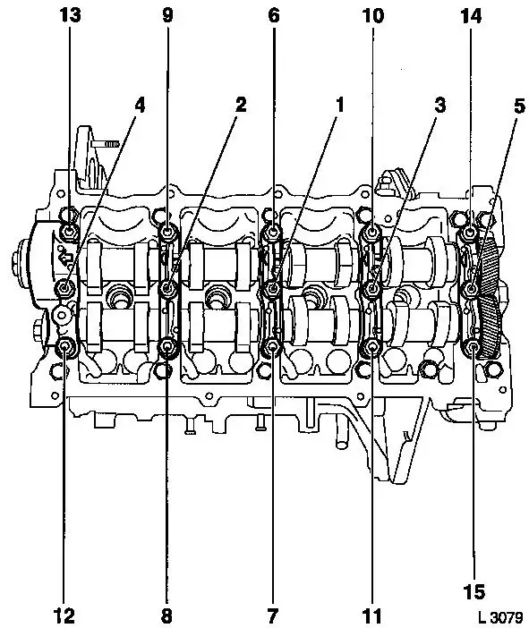
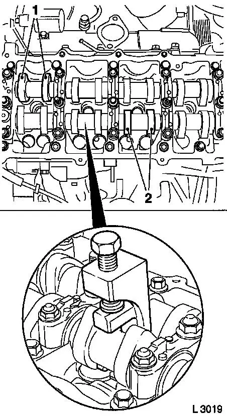
124. Rotate crankshaft
- Turn crankshaft until cam pairs (1) and (2) point upwards
|
|
125. Adjust valve clearance
- Turn cup tappet until tappet groove points outwards
- Press down cup tappets using KM-6090
- Note! Note different tool versions for intake and exhaust
valves
- Mark – IN = Intake side
- Mark – EX = Exhaust side
- Caution! Ensure that valves do not interfere with piston
head
- Remove adjustment shim
Example for determination of shim
thickness
|
1.
|
Thickness of installed shim
|
|
3.15 mm
|
|
2.
|
Measurement between cam and cup tappets
|
+
|
0.45 mm
|
|
|
|
=
|
3.60 mm
|
|
3.
|
Nominal valve play
|
-
|
0.40 mm
|
|
4.
|
Thickness of new shim
|
=
|
3.20 mm
|
|
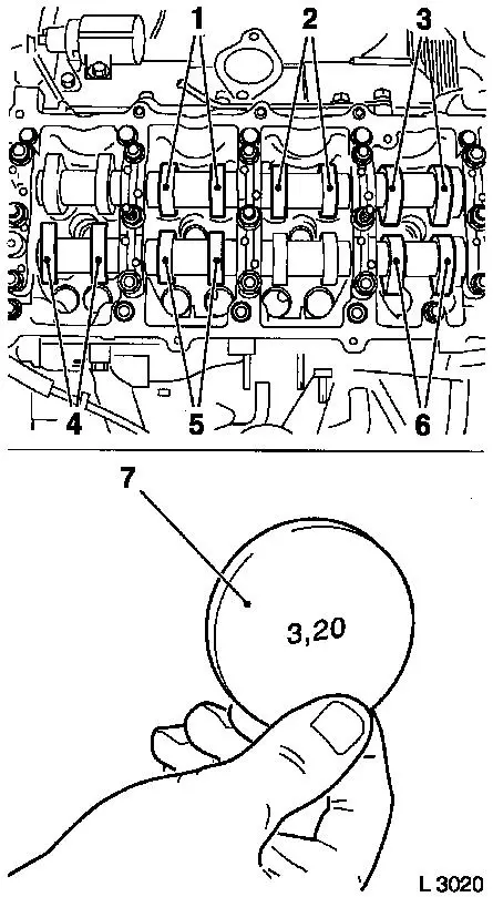
126. Insert adjustment shim
- Insert new shim (7), coat with engine oil, and insert in cup
tappet with identification mark facing downwards
- Note! Valve clearances must be checked again for all adjusted
valves
127. Rotate crankshaft
- In direction of engine rotation by 180°
- Check and adjust valve pair (6) and (2)
- In direction of engine rotation by 180°
- Check and adjust valve pair (5) and (3)
- In direction of engine rotation by 180°
- Check and adjust valve pair (4) and (1)
- Note! Valve clearances must be checked again for all adjusted
valves
|
|
128. Install diesel injection
nozzles
- Renew seal rings
- Renew copper sealing washers
- Insert diesel injection nozzles into cylinder head
- Attach injection nozzle bracket
- Tighten nuts (22.1 Nm / 16.3 lbf. ft.)
129. Attach inner oil leak line
- Renew seal rings
- Tighten banjo bolt (14.7 Nm/10.8 lbf. ft.)
130. Attach lower part of toothed belt cover
- Tighten bolts (9.8 Nm / 7.2 lbf. ft.)
131. Attach right engine bracket
- Insert lower bolt
- Into right engine bracket and right engine bracket adapter
- Insert right engine bracket, right engine bracket adapter,
upper part of toothed belt cover
- Install 2 upper bolts
- Tighten 3 bolts (40 Nm / 29.5 lbf. ft.)
132. Fasten upper part of toothed belt cover
- Tighten bolts (9.8 Nm / 7.2 lbf. ft.)
- Note! Note different bolt lengths
133. Attach coolant pump ribbed V-belt pulley
134. Raise vehicle
135. Install torsional vibration damper
- Tighten bolts (19.6 Nm / 14.5 lbf. ft.)
136. Install ribbed V-belt
137. Fasten coolant pump ribbed V-belt pulley
- Tighten bolts (9.8 Nm / 7.2 lbf. ft.)
138. Lower vehicle
|
139. Install right engine damping block
- To side member
- Tighten bolts (40 Nm / 29.5 lbf. ft.)
- On engine bracket
- Tighten bolts (60 Nm/44 lbf. ft + 30° + 15°.)
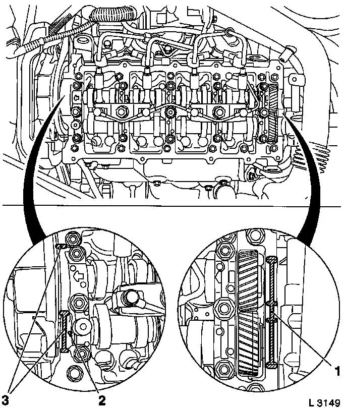
140. Install camshaft housing cover.
- Replace gasket
- Apply adhesive sealant compound (white)
- Caution! Oil return bore (2) must not be covered with adhesive
sealing compound or by the camshaft housing cover gasket
- Tighten bolts, studs (9.8 Nm/7.2 lbf. ft.)
|
|
141. Attach injection nozzle outer seals
- Replace seals
- Note! Note identification
- Tighten bolts
142. Attach injection line
- To diesel injection pump
- To injection nozzles
- Tighten union nuts (22.5 Nm/16.6 lbf. ft.)
143. Fasten left rear engine transport shackles
- Tighten bolt (20 Nm / 15 lbf. ft.)
144. Install right rear engine transport shackles
- Tighten bolt (20 Nm / 15 lbf. ft.)
145. Install engine control unit bracket
- Tighten bolts (24.5 Nm/18.1 lbf. ft.)
- Tighten nut (9.8 Nm/7.2 lbf. ft.)
- Attach wiring harness
146. Install engine control unit
- Tighten bolts, nuts (5.9 Nm/4.4 lbf. ft.)
- Install wiring harness plug bracket
- Connect wiring harness plug.
- Attach wiring harness
147. Connect wiring harness plug for engine control unit
148. Attach wiring trough
- Clip-in wiring trough
- Clip in vacuum lines
- Tighten bolt
149. Install oil dipstick guide tube bracket
- Tighten nuts
- Fasten oil dipstick guide tube
- Clip in vacuum hose
150. Install air intake pipe
- Tighten bolts
- Attach engine vent hose
- Attach wiring harness
151. Install air cleaner housing
- Tighten bolt
- Fasten air intake hose.
- Fasten clamp (3.5 Nm / 2.6 lbf. ft.)
- Connect wiring harness plug to hot film mass air flow
meter
152. Raise vehicle
153. Detach support
154. Detach KM-6169
155. Attach ribbed V-belt cover
- Tighten bolts
- Install clips
156. Lower vehicle
157. Install right front wheel
158. Lower vehicle
159. Fasten right front wheel
- Tighten bolts (110 Nm / 81 lbf. ft.)
160. Check and correct engine oil level
- Check engine oil level, if necessary correct.
- Observe specified engine oil quantity
161. Connect battery
162. Calibrate steering angle sensor
Note: Rotate the
steering wheel one time from its right-hand to its left-hand
stop.
163. Top up coolant
- Note! Top up and bleed cooling system – see operation
"Top up and bleed cooling system"
- Observe specified coolant quantity
164. Program volatile memories
164. Close bonnet
|
