|
Valve Clearance, Check and Adjust (Y 17 DTL)
Condition:
Timing checked – see operation "Timing, Check".
|
1. Open bonnet
Important: On
vehicles from model year 04 with ESP - the steering angle sensor
loses its basic adjustment each time the battery is disconnected.
It must be recalibrated.
2. Disconnect battery
|
|
|
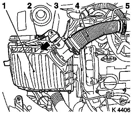
3. Remove air cleaner housing (1)
- Remove wiring harness plug for hot film mass air flow meter
(3)
- Release in direction of arrow
- Remove air intake hose (4)
- Remove bolt (2)
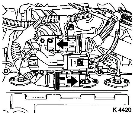
4. Remove wiring harness plug for engine management
- 3 off
- Release 2 wiring harness plugs in direction of arrow
|
|
|
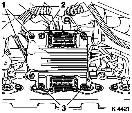
5. Remove engine control unit
- Remove wiring harness plug bracket
- Unscrew 2 bolts (2), 2 nuts (3)
|
|
|
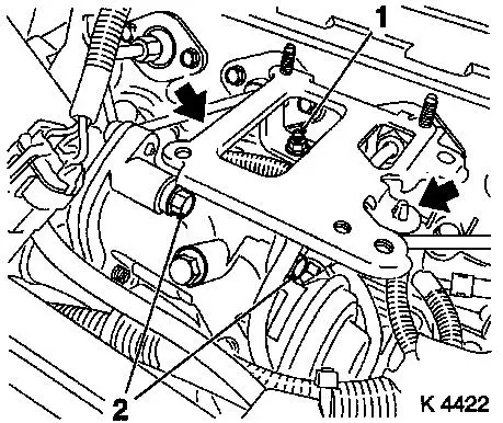
6. Remove engine control unit bracket
- Unscrew 2 bolts (2), nut (1)
- Unclip wiring harness (arrows)
7. Remove right rear engine transport shackle
8. Loosen left rear engine transport shackle
9. Remove injection lines
|
|
|
10. Remove outer injector nozzle seals
11. Remove oil dipstick guide tube bracket
|
|
|
12. Detach alternator wiring harness
- Disconnect wiring harness plug
- Unscrew nut
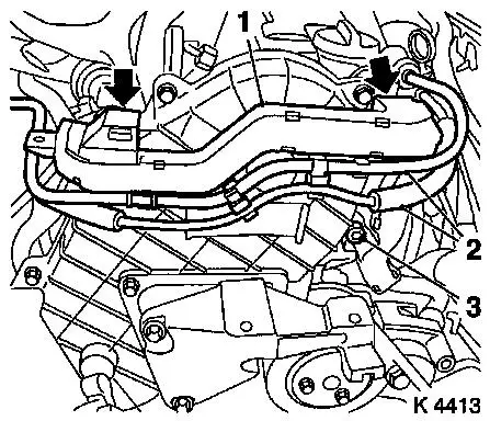
13. Remove wiring trough (1)
- Unclip vacuum lines (2)
- Unclip wiring trough
- Remove bolt
|
|
|
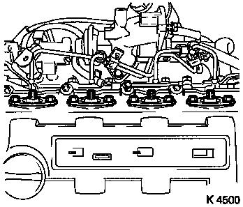
14. Remove camshaft housing cover
- Unscrew 7 bolts (1), 3 studs (2)
15. Remove camshaft housing cover
- Note! 2. mechanic
- Carefully push injection lines to rear
- Remove engine vent hose
|
|
|
16. Detach inner oil leak line
- Remove 5 banjo bolts
- Note! Note sealing rings
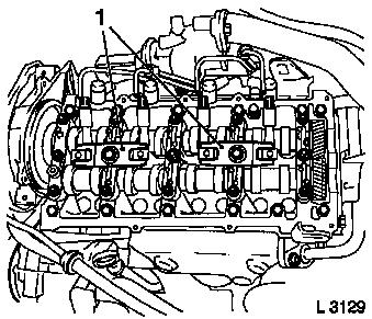
17. Remove injector nozzles
- Remove injection nozzle bracket (1)
- Remove injector nozzles
|
|
|
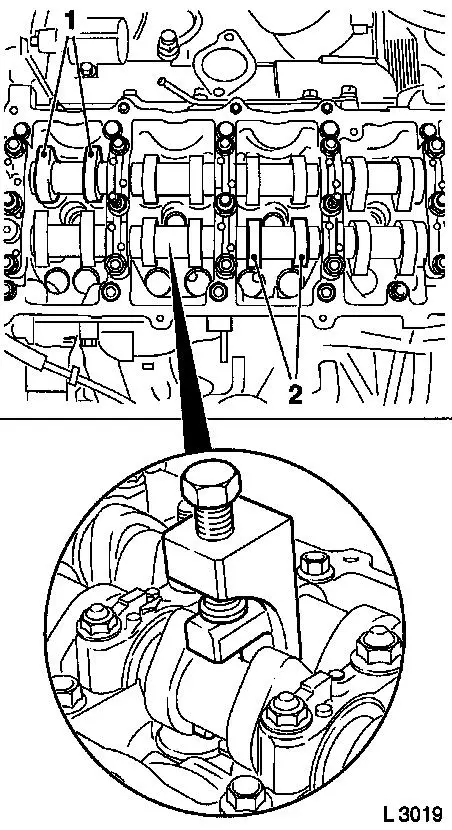
18. Turn crankshaft
- Turn crankshaft until cam pairs (1) and (2) point upwards
19. Check valve clearance
- Using feeler gauge
- Test values: Intake valve/Exhaust valve (0.35 – 0.45
mm)
- Note! The valve clearances are checked on a cold engine –
room temperature
20. Adjust valve clearance
- Turn cup tappet until tappet groove points outwards
- Press down cup tappets using KM-6090
- Note! Note different tool versions for intake and exhaust
valves
- Mark – IN = Intake side
- Mark – EX = Exhaust side
- Caution! Ensure that valves do not interfere with piston
head
- Remove adjustment shim
|
|
|
Example for determination of shim
thickness
|
1.
|
Thickness of installed shim
|
|
3.15 mm
|
|
2.
|
Measurement between cam and cup tappets
|
+
|
0.45 mm
|
|
|
|
=
|
3.60 mm
|
|
3.
|
Nominal valve play
|
-
|
0.40 mm
|
|
4.
|
Thickness of new shim
|
=
|
3.20 mm
|
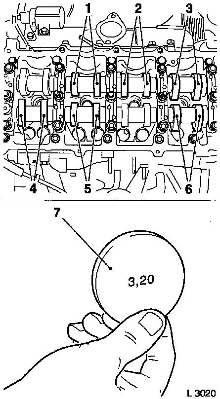
21. Insert adjustment shim
- Coat new shim (7) with engine oil and insert in cup tappet with
identification mark facing downwards.
22. Turn crankshaft
- In direction of engine rotation by 180°
- Check and adjust valve pair (6) and (2)
- In direction of engine rotation by 180°
- Check and adjust valve pair (5) and (3)
- In direction of engine rotation by 180°
- Check and adjust valve pair (4) and (1)
- Note! Valve clearances must be checked again for all adjusted
valves
|
|
23. Install injector nozzles
- Renew seal rings
- Renew copper sealing washers
- Insert injection nozzles in cylinder head.
- Install injector nozzle bracket (22.1 Nm/16.3 lbf. ft.)
24. Attach inner oil leak line
- Renew seal rings
- Tighten banjo bolt (14.7 Nm / 10.8 lbf. ft.)
|
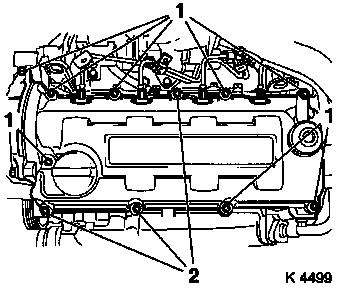
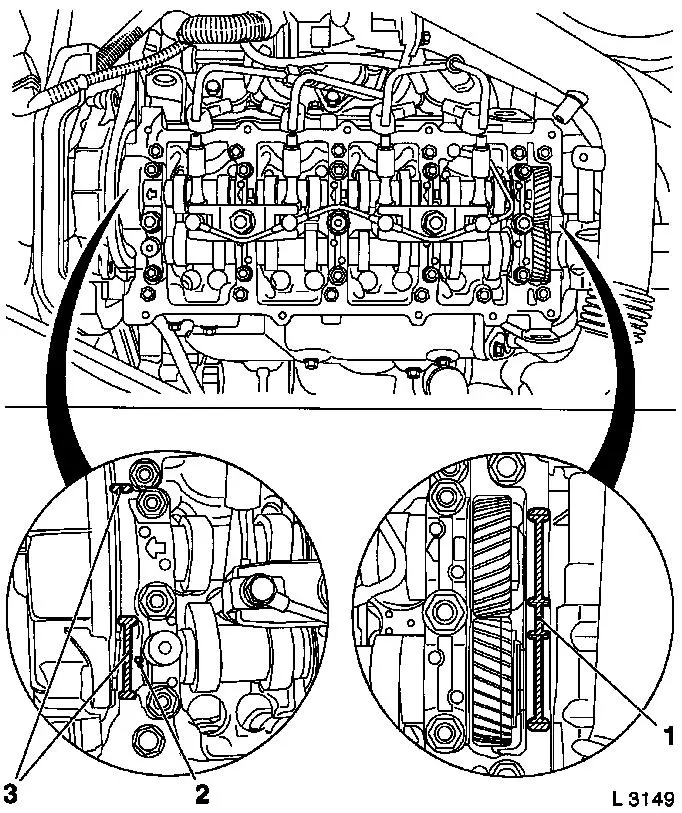
25. Install camshaft housing cover.
- Replace gasket
- Apply adhesive sealant compound (white)
- Caution! Oil return bore (2) must not be covered with adhesive
sealing compound or by the camshaft housing cover gasket
26. Install camshaft housing cover
- Note! 2. mechanic
- Carefully push injection line to rear
27. Tighten camshaft housing cover
- Tighten bolts, studs (9.8 Nm/7.2 lbf. ft.)
28. Attach engine vent hose
|
|
29. Install oil dipstick guide tube bracket
30. Install outer injector nozzle seals
- Replace seals
- Tighten bolts
31. Install injection lines
- Tighten union nuts (22.5 Nm/16.6 lbf. ft.)
32. Fasten left rear engine transport shackle
- Tighten bolts (20 Nm / 15 lbf. ft.)
33. Install right rear engine transport shackle
- Tighten bolts (20 Nm / 15 lbf. ft.)
34. Attach wiring trough
- Clip-in wiring trough
- Clip in vacuum lines
- Tighten bolt
35. Attach alternator wiring harness
- Connect wiring harness plug.
- Tighten nuts
36. Install engine control unit bracket
- Tighten bolts (24.5 Nm/18.1 lbf. ft.)
- Tighten nut (9.8 Nm/7.2 lbf. ft.)
- Attach wiring harness
37. Install engine control unit
- Tighten bolts, nuts (5.9 Nm/4.4 lbf. ft.)
- Install wiring harness plug bracket
38. Attach engine control unit wiring harness plug
39. Install air cleaner housing
- Tighten bolt
- Fasten air intake hose.
- Tighten clamp (3.5 Nm / 2.6 lbf. ft.)
- Connect wiring harness plug to hot film mass air flow
meter
40. Connect battery
41. Calibrate steering angle sensor
Note: Rotate the
steering wheel one time from its right-hand to its left-hand
stop.
42. Program volatile memories
43. Close bonnet
|
