|
Camshaft Housing, Replace (Z 17 DTH, without AC,
LHD)
 Remove Remove
| 1. |
Remove camshaft housing cover 
|
| 2. |
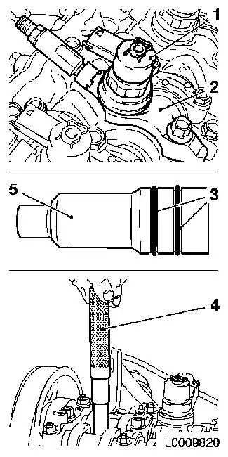
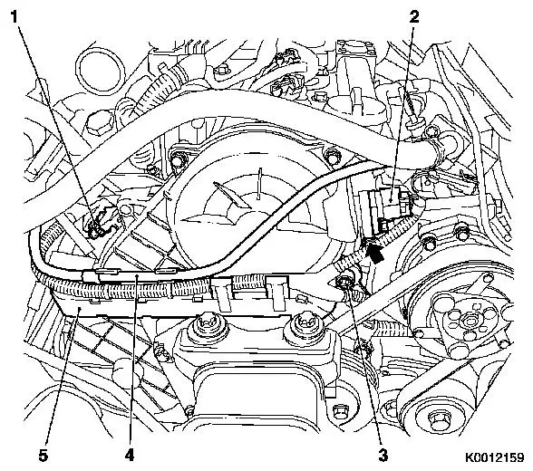
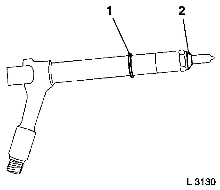
Remove 4 injectors
Note: Mark 4x injectors
(1)
Important: If the heat insulation
sleeve (5) is also pulled out together with the injector during
removal, new gaskets (3) must be installed and the heat insulation
sleeve driven into the cylinder head using KM-6357 (4)
|
| • |
Remove 4 injector brackets (2)
|
|
|
|
| 3. |
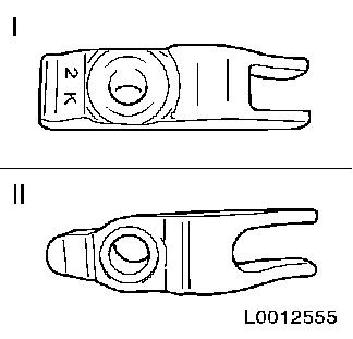
Check injector bracket
Note: If an old
injector bracket was installed, it must be replaced with a new
one
- New injector bracket
- Old injector bracket
|
|
|
| 4. |
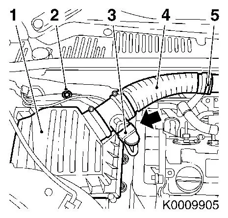
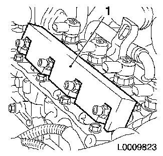
Remove air cleaner housing (1)
| • |
Disconnect wiring harness plug of hot film mass air flow meter
(3)
| – |
Release in direction of arrow
|
|
| • |
Remove air intake hose (4)
|
| • |
Disconnect wiring harness
|
|
|
|
| 6. |
Remove ribbed V-belt cover
|
|
|
|
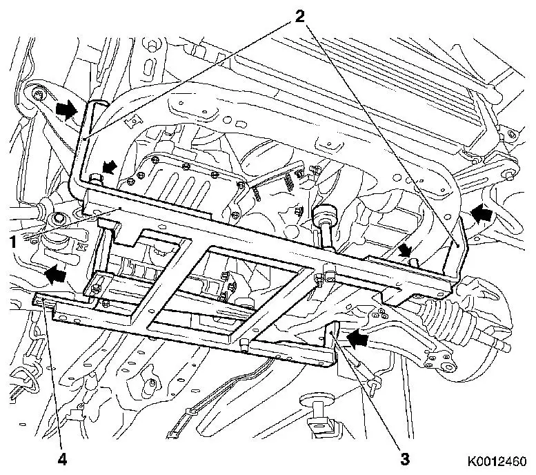
| 7. |
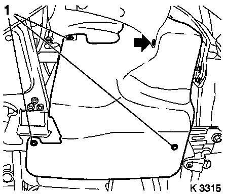
Attach KM-6394
| • |
Position KM-6394 (1) at the front on
the front axle body
Note: Both locating
pins (arrows) must be seated in the holes in the front axle
body
|
| • |
Push front bracket (2) in the direction of the arrow
|
| • |
Place rear bracket (4), right hand side, on front axle body
|
| • |
Attach rear bracket (3), left hand side
|
|
|
|
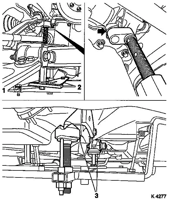
| 8. |
Install support
| • |
On KM-6394
| – |
Adjust bracket (2) for support
|
|
|
| 9. |
Adjust 3x support
| • |
Transmission side
Note: Turn spindles
until mounts (3) are positioned at guide journals free of play
|
| • |
Engine timing side
| – |
Insert journal of the support in the bore of the cylinder block
free of play (arrow)
|
|
|
|
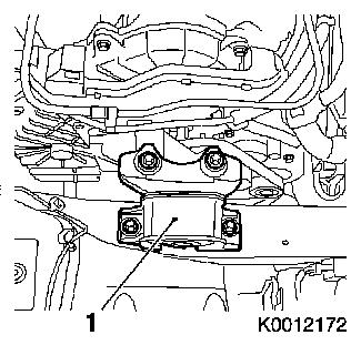
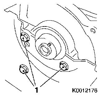
| 11. |
Remove right engine damping block (1)
|
|
|
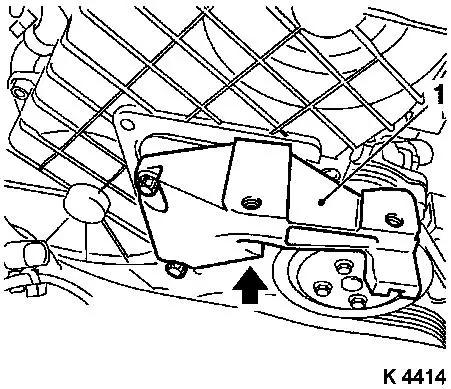
| 12. |
Detach right engine bracket (1)
| • |
Unscrew 3 bolts
Note: Lower bolt cannot
be removed
|
| • |
With right engine bracket adapter
|
|
|
|
|
| 13. |
Detach wiring trough of engine management wiring harness
| • |
Unclip wiring trough (5)
|
| • |
Disconnect 2 wiring harness plugs
| – |
Charge pressure sensor (1)
|
|
|
|
| 14. |
Remove camshaft sensor bracket
|
| 15. |
Remove upper toothed belt cover
Important: Take care not to
damage the increment counter on the camshaft sprocket when removing
the upper toothed belt cover
|
| • |
Unscrew 8 bolts
Note: Pay attention to
different bolt lengths
|
|
|
|
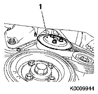
| 17. |
Loosen coolant pump ribbed V-belt pulley (1)
|
|
|
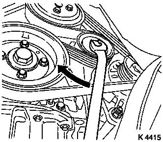
| 18. |
Remove ribbed V-belt
| • |
Tension ribbed V-belt tensioner in direction of arrow
|
| • |
Use KM-913-A
Note: Mark running
direction.
|
|
|
|
| 19. |
Detach coolant pump ribbed V-belt pulley
|
| 20. |
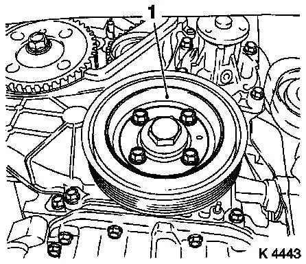
Remove torsional vibration damper (1)
|
|
|
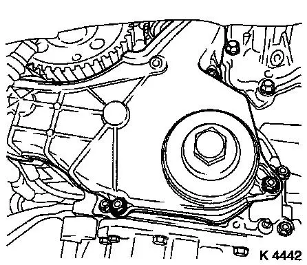
| 21. |
Detach lower part of toothed belt cover
|
|
|
| 22. |
Remove right engine bracket with right engine bracket
adapter
|
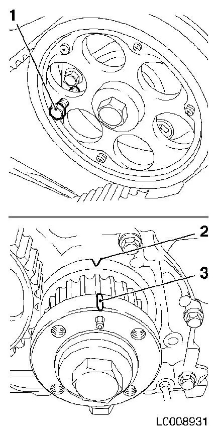
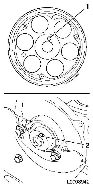
| 24. |
Set 1st cylinder to TDC
| • |
Turn crankshaft evenly until TDC fixing bolt (1) can be screwed
in
Note: Mark (3) on
toothed belt drive gear must align with mark (2) on oil pump
cover
|
|
|
|
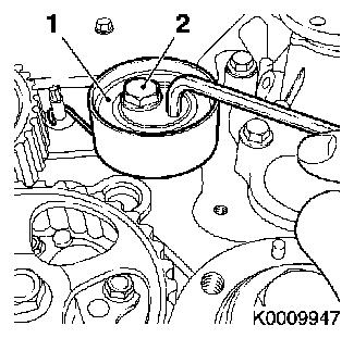
| 26. |
Loosen toothed belt tension roller (1)
| • |
Loosen bolt of toothed belt tension roller (2)
|
| • |
Rotate toothed belt tension roller anticlockwise approx.
90°
|
| • |
Tighten bolt of toothed belt tension roller
|
|
|
|
| 27. |
Remove toothed belt
Note: Mark running
direction.
|
| 28. |
Remove toothed belt guide roller
|
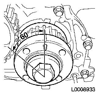
| 30. |
Rotate crankshaft 60° against direction of engine
rotation
|
|
|
| 31. |
Detach camshaft pulley
| • |
Unscrew TDC fixing bolt (1)
|
| • |
Use KM-6347 (3) in combination with
KM-956-1 (2)
|
|
|
|
| 32. |
Detach connection hose (1) from intercooler for intake pipe
|
|
|
|
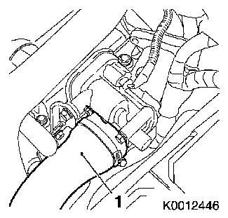
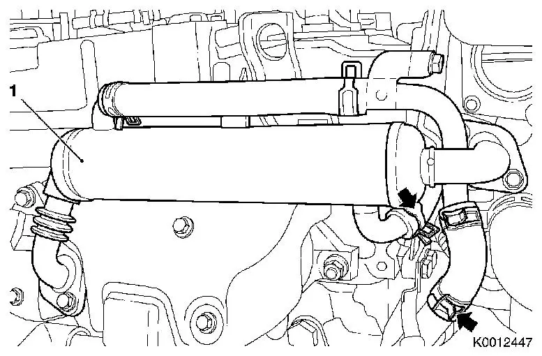
| 33. |
Detach EGR cooler (1)
| • |
Release 2 clamps (arrows)
|
|
|
| 34. |
Front left engine transport shackle
|
| 35. |
Remove throttle valve module bracket
|
| 36. |
Detached rear toothed belt cover from camshaft housing
|
|
|
|
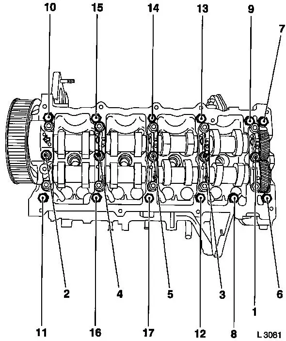
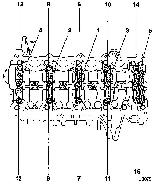
| 37. |
Remove camshaft housing
| • |
Loosen 17 bolts 1/2 turn in sequence illustrated and
unscrew
|
|
|
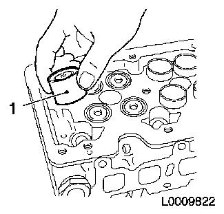
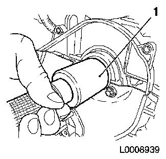
| 38. |
Remove 16 cup tappets (1)
Note: Note order and
installation position
|
|
|
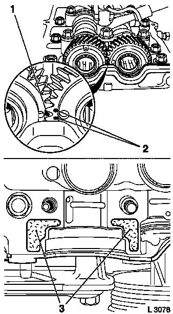
| 39. |
Lock exhaust camshaft compensating sprocket
| • |
Remove camshaft bearing cap (3)
|
| • |
Use KM-6092-10 (1)
Note: Insert into
exhaust camshaft sprocket (4) and exhaust camshaft compensating
sprocket (2) as far as it will go. Exhaust camshaft sprocket and
exhaust camshaft compensating sprocket must be locked so they
cannot turn
|
|
|
|
| 40. |
Remove 2x camshaft
Note: Note markings on
camshaft bearing caps
| • |
Remove front camshaft seal ring
|
|
| 41. |
Clean sealing surfaces
|
 Install
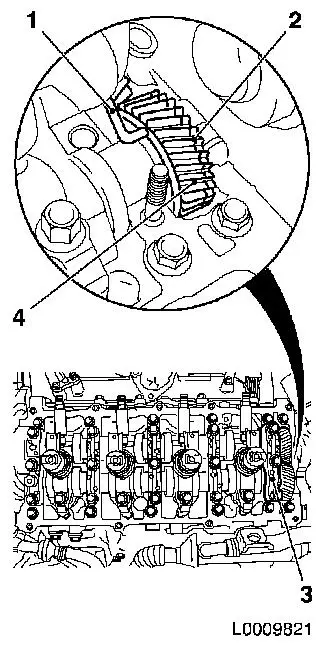
Important: When installing the
camshafts, care must be taken that the marking (1) on the exhaust
camshaft sprocket is between the two markings (2) for the intake
camshaft sprocket and that the markings are approximately on the
same level as the upper edge of the camshaft housing.
|
| 43. |
Install 2x camshaft
| • |
Insert camshaft in camshaft housing
|
| • |
Apply surface sealant (green) to the sealing surfaces (3) of
the 1st camshaft bearing cap
|
|
|
|
|
| 44. |
Install 5 camshaft bearing caps
Note: Coat bearing
positions with engine oil
| • |
Fit camshaft bearing caps (1 - 4)
|
| • |
Fit camshaft bearing cap (5)
|
| • |
Tighten camshaft bearing caps
| – |
10 nuts (M8) 21.6 Nm
Note: Tighten camshaft
bearing caps in stages of 1/2 to 1 turn in the order shown
|
|
|
|
| 45. |
Install front camshaft seal ring
|
|
|
| 46. |
Insert 16x cup tappet
Note: Observe
allocation.
|
|
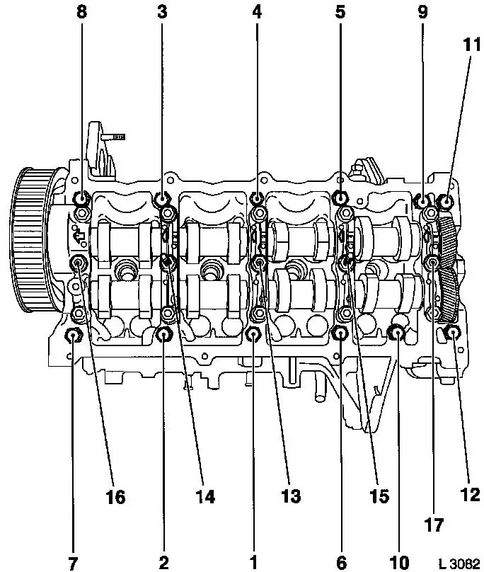
| 47. |
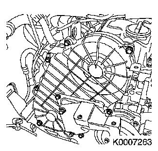
Install camshaft housing
| • |
Replace gasket
Note: Note tightening
sequence (1 - 17)
| – |
Tighten 12 bolts 21.6 Nm
|
| – |
Tighten 5 bolts 26.5 Nm
|
|
|
|
| 48. |
Attach rear toothed belt cover
|
| 49. |
Install bracket for throttle valve module
|
| 50. |
Install front left engine transport shackle
|
| 51. |
Attach EGR cooler
| • |
To connection, exhaust return pipe, exhaust manifold
| – |
Tighten 4 bolts 28.5 Nm
|
|
|
| 52. |
Attach connection hose of intercooler to intake pipe
|
Warning: The different camshaft
sprockets (with different part numbers) have different torques for
the camshaft sprocket bolt.
|
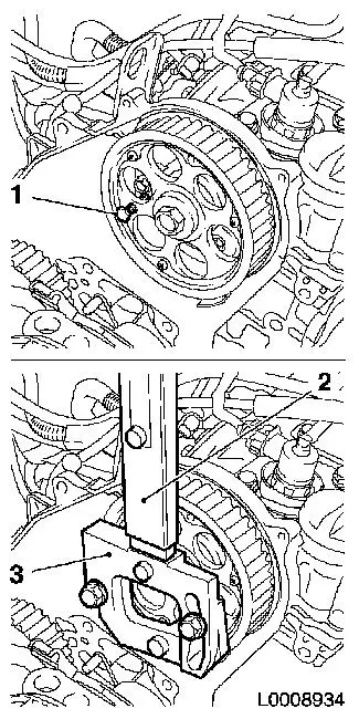
| 53. |
Attach camshaft sprocket with part number 97320335
| • |
Camshaft journal (2) must engage in the bore in the camshaft
sprocket (1)
|
| • |
Use KM-6347 in combination with KM-956-1
|
| • |
Install TDC-fixing bolt
|
|
| 54. |
Attach camshaft sprocket with part number 98021306
| • |
Camshaft journal (2) must engage in the bore in the camshaft
sprocket (1)
|
| • |
Use KM-6347 in combination with KM-956-1
|
| • |
Install TDC-fixing bolt
|
|
|
|
| 56. |
Rotate crankshaft to 1st cylinder TDC
| • |
Mark on toothed belt drive gear (3) must align with cast lug
(2) on oil pump cover
|
|
|
|
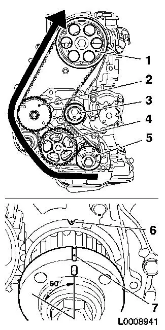
| 57. |
Install toothed belt
Note: TDC locking bolt
must be installed in the camshaft sprocket and marking (6) and (7)
must align.
| • |
Position toothed belt
| – |
Toothed belt must be tensioned in the direction of the arrow
from the toothed belt drive gear (5) via the oil pump drive gear
(4), via the high pressure pump drive gear (2) to the camshaft
sprocket (1)
|
|
| • |
Loosen toothed belt tension roller (3)
|
| • |
Remove TDC locking bolt
|
| • |
Rotate crankshaft 60° against direction of engine
rotation
|
| • |
Tighten toothed belt tension roller 38Nm
|
|
|
|
| 58. |
Timing, Check
| • |
Turn crankshaft approx. 780° in direction of engine
rotation
|
| • |
Mark on toothed belt drive gear (3) must align with cast lug
(2) on oil pump cover
|
| • |
Screw in TDC fixing bolt (1)
Note: If the TDC fixing
bolt cannot be screwed in, basic adjustment must be repeated
|
| • |
Unscrew TDC fixing bolt
|
|
|
|
| 60. |
Install right engine bracket
| • |
Fit right engine bracket with adapter
|
| • |
Insert and tighten lower bolt
|
|
| 61. |
Attach lower part of toothed belt cover
|
| 62. |
Install torsional vibration damper
| • |
Tighten 4 bolts 19.6 Nm
|
|
| 63. |
Attach coolant pump ribbed V-belt pulley
|
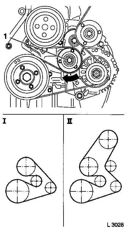
| 64. |
Install ribbed V-belt
Note: Observe running
direction and installation position
| • |
Relieve tension of ribbed V-belt tensioner (1) in the direction
of the arrow
|
| • |
Use KM-913
| – |
I Ribbed V-belt without AC
|
| – |
II Ribbed V-belt with AC
|
|
|
|
|
| 65. |
Fasten coolant pump ribbed V-belt pulley
| • |
Tighten 3 bolts 16.3 Nm
|
|
| 67. |
Install camshaft sensor bracket
|
| 68. |
Install upper toothed belt cover
| • |
Tighten 8 bolts 9.8 Nm
Note: Note different
bolt lengths
|
|
| 69. |
Attach wiring trough of engine management wiring harness
| • |
Connect 2 wiring harness plugs
|
|
| 70. |
Fasten right engine bracket
| • |
Tighten 2 upper bolts 40 Nm
|
|
| 71. |
Install right engine damping block
| • |
On engine bracket
| – |
Tighten 2 bolts 60 Nm + 30° +
15°
|
|
|
| 73. |
Fasten right engine bracket
| • |
Tighten lower bolt 40 Nm
|
|
| 76. |
Attach ribbed V-belt cover
|
| 78. |
Install air cleaner housing
| • |
Fasten air intake hose.
|
| • |
Connect wiring harness plug of hot film mass air flow meter
|
|
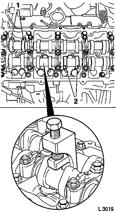
| 79. |
Turn crankshaft
| • |
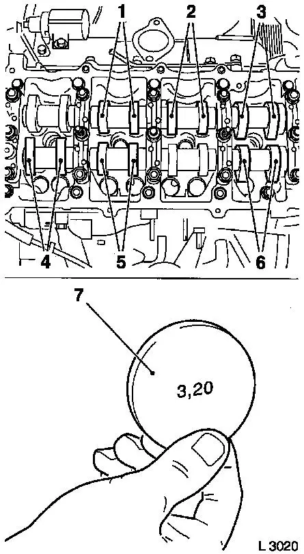
Turn crankshaft until cam pairs (1) and (2) point upwards
|
|
|
|
| 80. |
Check valve clearance
| • |
Using feeler gauge
Note: The valve play is
checked on a cold engine – room temperature.
| – |
Test values: Intake valves/Exhaust valves (0.35 – 0.45
mm)
|
|
|
| 81. |
Adjust valve clearance
| • |
Turn cup tappet until tappet groove points outwards
|
Important: Make sure that the
valves are not set when the piston is in "TDC". The valves could
strike the piston head
|
| • |
Press down cup tappets
Note: Note different
tool versions for intake and exhaust valves
| – |
Mark – IN = Intake side
|
| – |
Mark – EX = Exhaust side
|
|
|
|
|
| 82. |
Example for determination of shim thickness:
|
1. Thickness of installed shim
|
3.15 mm
|
|
2. Measurement between cam and cup tappets
|
+ 0.45 mm
|
| |
= 3.60 mm
|
|
3. Nominal valve clearance
|
- 0.40 mm
|
|
| 83. |
Insert adjustment shim
| • |
Coat new shim (7) with engine oil and insert in cup tappet with
identification mark facing downwards
|
|
| 84. |
Turn crankshaft
| • |
In direction of engine rotation by 180°
| – |
Check and adjust valve pair (6) and (2)
|
|
| • |
In direction of engine rotation by 180°
| – |
Check and adjust valve pair (5) and (3)
|
|
| • |
In direction of engine rotation by 180°
| – |
Check and adjust valve pair (4) and (1)
Note: The clearance of
all adjusted valves must be re-checked
|
|
|
|
|
| 85. |
Detach accumulator
| • |
Unscrew 2x bolts 1 - 1 1/2 turns
|
|
| 86. |
Replace 8 injector seals
| • |
4 copper seal rings (2)
|
|
|
|
| 87. |
Install 4 injectors
| • |
Install 4x brackets
| – |
Align injectors with EN-48560 (1)
|
|
|
|
|
| 88. |
Fasten 4x accumulator high pressure lines to injectors
| • |
Hand-tighten 8x union nuts
|
|
| 89. |
Fasten 4x injectors
| • |
Tighten 4 bolts in three stages
|
|
|
|
| 91. |
Remove 4x accumulator high pressure lines at injectors
| • |
Seal off connections of accumulator using suitable sealing
plugs
|
| • |
Seal off connections of injectors with protective caps
|
|
| 92. |
Install camshaft housing cover
Note: See operation
"Camshaft Housing Cover, Remove".
|
|
