|
Replace valve stem seals
 Remove Remove
| 1. |
Remove camshaft housing
|
| 2. |
Remove roller cam follower with hydraulic valve lifter 
|
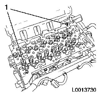
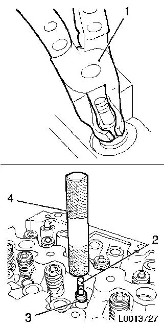
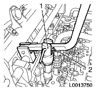
| 3. |
Remove 2 x camshaft housing centring pins (1)
|
|
|
| 4. |
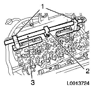
Attach MKM-6086
| • |
Adjust 2 supports MKM-6086-6 1
| – |
Set support heads on outside of support feet
|
|
| • |
Slide joint MKM-6086-8 (2) onto
mounting shaft MKM-6086-4 (3)
| – |
Slide 2 supports MKM-6086-6 onto the
mounting shaft MKM-6086-4
|
|
| • |
Attach both supports with the mounting shaft to the cylinder
head
Important: Note screw length of
blind hole thread
|
| – |
Screw in 4 bolts
|
|
|
|
|
Important: Note screw length of
blind hole thread
|
| 5. |
Attach EN-46782 together with EN-46783 (2) and MKM-6086-17 (1) to cylinder 1
| • |
Fit EN-46782 with gasket and injector
(4) on cylinder 2
|
|
|
|
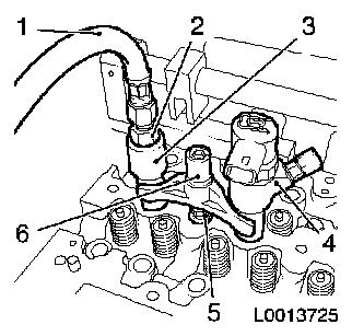
| 6. |
Attach lever arm
| • |
Attach lever arm MKM-6086-7 (3)
together with adapter MKM-6086-12 (2) and
removal head MKM-6086-11 (4) to joint
MKM-6086-8 (1)
|
|
Important: Check that compressed
air is being applied
|
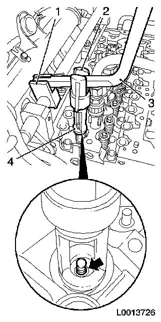
| 7. |
Remove 2 cylinder no.1 intake valve springs
Important: Removal head must be
vertically above the valve stem
|
| • |
Carefully push valve spring down with lever arm MKM-6086-7
|
| • |
Remove 2 split cotters (arrow)
|
| • |
Remove valve heads and valve springs
|
|
|
|
| 8. |
Replace 2x valve stem seals
| • |
Detach using KM-840 (1)
|
| • |
Attach new valve stem seal (3) to valve stem (2)
Note: Moisten new valve
stem seals with oil.
|
| • |
Using EN-46779 (4), drive in as far
as the stop
|
|
|
|
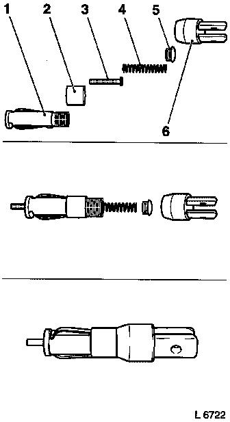
| 9. |
Complete the assembly head MKM-6086-100-1
Note: Follow
manufacturer's instructions.
| • |
Assemble the assembly head, which consists of a mount (1),
securing sleeve (2), thrust piece MKM-6086-13 (3), spring (4), screwed connection (5)
and lever mount MKM-6086-12 (6)
|
|
|
|
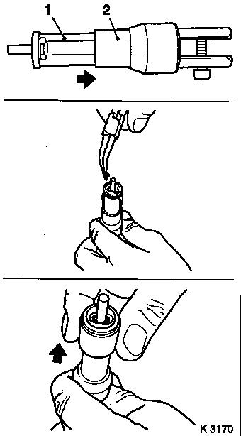
| 10. |
Install 2 intake valve springs, cylinder 1
| • |
Insert valve springs and caps
|
| • |
Insert valve keepers in assembly head MKM-6086-100-1 (1)
Important: Insert valve keepers
with taper facing the valve.
|
| – |
Slide clamping sleeve (2) in direction of lever arm mount
|
| – |
Push clamping sleeve towards valve
|
|
| • |
Attach assembly head to lever arm
|
|
|
|
Important: Check that compressed
air is being applied
|
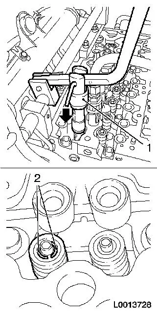
| 11. |
Install valve keepers
Important: Assembly head (1) must
be vertically above the valve stem. Valve keepers (2) must engage
audibly.
|
| • |
Carefully push valve springs downwards (arrow)
|
Important: Do not make 2nd
attempt without checking that both valve keepers are in the
assembly head.
|
| • |
Check seat of valve keepers (2)
|
|
|
|
| 12. |
Attach removal head MKM-6086-11 to
adapter MKM-6086-12 .
|
| 13. |
Mount adapter (1) on hole (2)
|
|
|
| 14. |
Remove 2 valve springs from cylinder 1 exhaust valve
|
| 15. |
Replace valve stem seal
|
| 16. |
Attach removal head MKM-6086-100-1 to
adapter MKM-6086-12 .
|
| 17. |
Install 2 valve springs to cylinder 1 exhaust valve
|
| 18. |
Attach EN-46783 to cylinder 2
| • |
Interrupt compressed air feed
|
| • |
Remove EN-46782 with injector from
cylinder 2
|
| • |
Install EN-46782 in cylinder 2
| – |
Insert cylinder 1 with injector
|
|
| • |
Apply compressed air to cylinder 2
|
|
| 19. |
Remove 2 valve springs from cylinder 1 exhaust valve
|
| 20. |
Replace valve stem seal
|
| 21. |
Install 2 valve springs to cylinder 1 exhaust valve
|
| 23. |
Remove 2 valve springs from cylinder 2 intake valve
|
| 24. |
Replace valve stem seal
|
| 25. |
Install 2 valve springs in cylinder 2 intake valve
|
| 26. |
Attach EN-46783 to cylinder 3
| • |
Interrupt compressed air feed
|
Important: Note screw length of
blind hole thread
|
| • |
Remove EN-46782 with injector from
cylinder 1
|
| • |
Install EN-46782 with gasket in
cylinder 3
| – |
Insert in cylinder 4 together with injector
|
|
| • |
Apply compressed air to cylinder 3
|
|
| 27. |
Remove 2 valve springs from cylinder3 intake valve
|
| 28. |
Replace valve stem seal
|
| 29. |
Install 2 valve springs in cylinder 3 intake valve
|
| 31. |
Remove 2 valve springs from cylinder 3 exhaust valve
|
| 32. |
Replace valve stem seal
|
| 33. |
Install 2 valve springs to cylinder 3 exhaust valve
|
| 34. |
Attach EN-46783 to cylinder 4
| • |
Interrupt compressed air feed
|
| • |
Remove EN-46782 with injector from
cylinder 4
|
| • |
Install EN-46782 in 4th cylinder
| – |
Insert cylinder 3 with injector
|
|
| • |
Apply compressed air to cylinder 4
|
|
| 35. |
Remove 2 valve springs from cylinder 4 exhaust valve
|
| 36. |
Replace valve stem seal
|
| 37. |
Install 2 valve springs to cylinder 4 exhaust valve
|
| 39. |
Remove 2 valve springs from cylinder 4 intake valve
|
| 40. |
Replace valve stem seal
|
| 41. |
Install 2 valve springs in cylinder 4 intake valve
|
| 42. |
Remove EN-46783 from cylinder 4
| • |
Interrupt compressed air feed
|
| • |
Remove EN-46782 with injector from
cylinder 3
|
|
 Install
| 44. |
Insert 2 camshaft housing centring pins
|
| 45. |
Install roller cam follower with hydraulic valve lifter
|
| 46. |
Install camshaft housing
|
|
