|
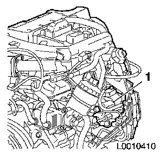
High-pressure pump - Z 17 DTH engine
The Z 17 DTH engine is fitted with the HP 3 high-pressure pump
from Denso.
The task of the high-pressure pump is to draw in fuel and make
available the required system pressure in the pressure
accumulator.
The admission pressure that the high-pressure pump requires to
operate is provided by the mechanical delivery pump incorporated
into the housing of the high-pressure pump.
The high-pressure pump works as a twin-acting plunger pump. It
is the interface between the low-pressure side and the
high-pressure side. It continually generates the system pressure
for the pressure accumulator.
The high-pressure pump is mounted rearwards on the timing case
and driven by the camshaft toothed belt.
• Service:
The Common Rail system of the Z 17 DTH engine does not need to be
bled after installation work. It is self-bleeding. To prevent the
starter from overheating, the bleed process must only be carried
out by actuating the starter continuously for 40 seconds maximum.
After that, a sufficient amount of time must elapse to enable the
starter to cool. The bleed process can be repeated if required.
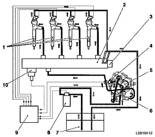
Diagram of fuel flow
|
| 1. |
Injectors |
| 2. |
Pressure accumulator |
| 3. |
Pressure limiter |
| 4. |
Fuel temperature sensor |
| 5. |
Metering unit |
| 6. |
High-pressure pump |
| 7. |
Fuel tank |
| 8. |
Fuel filter |
| 9. |
Engine control unit |
| 10. |
Fuel pressure sensor |
|
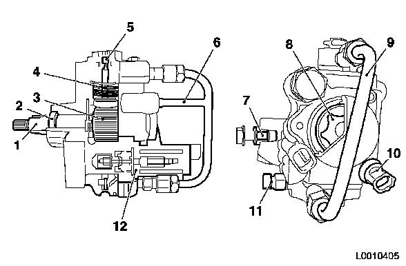
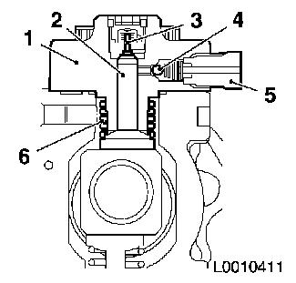
Diagram of high-pressure pump
|
- Side view
- Rear view
| 1. |
Eccentric shaft |
| 2. |
Shaft seal ring |
| 3. |
Polygonal ring |
| 4. |
Pump plunger |
| 5. |
Pump valve |
| 6. |
Fuel feed system |
| 7. |
Fuel return system |
| 8. |
Delivery pump |
| 9. |
High-pressure pipe |
| 10. |
Fuel temperature sensor |
| 11. |
High-pressure connection |
| 12. |
Metering unit |
|
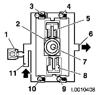
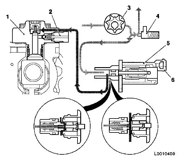
Functional diagram of the high-pressure pump
| 1. |
Metering unit |
| 2. |
Polygonal ring |
| 3. |
Valve - intake side |
| 4. |
Valve - delivery side |
| 5. |
Pump plunger |
| 6. |
High fuel pressure |
| 7. |
Eccentric shaft |
| 8. |
Pump plunger |
| 9. |
Valve - delivery side |
| 10. |
Valve - intake side |
| 11. |
Fuel feed |
|
|
Diagram of pump element
| 1. |
Pump element |
| 2. |
Pump plunger |
| 3. |
Valve - intake side |
| 4. |
Valve - high-pressure side |
| 5. |
Holder - high-pressure pipe |
| 6. |
Spring - pump plunger |
|
|
Metering unit
The metering unit regulates the system pressure in the pressure
accumulator by limiting the quantity of fuel in the high-pressure
pump. The metering unit is incorporated into the high-pressure pump
and is actuated by the engine control unit.
Diagram of metering unit
|
- Metering unit, not actuated, low delivery quantity
- Metering unit, actuated, high delivery quantity
| 1. |
High-pressure pump |
| 2. |
Holder - high-pressure pipe |
| 3. |
Delivery pump |
| 4. |
Pressure regulating valve, pre-supply pump |
| 5. |
Metering unit |
| 6. |
Electrical connection |
|
Pressure limiter
The mechanical pressure limiter is installed in the pressure
accumulator. It limits the maximum pressure in the pressure
accumulator.
|