|
Engine with Transmission, Remove and Install
 Remove Remove
Important: On vehicles as of
model year 04 with ESP - every time the battery is disconnected,
the steering angle sensor loses its basic setting. It must be
recalibrated.
|
| 2. |
Disconnect battery
|
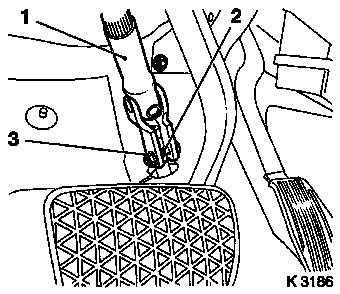
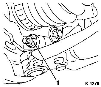
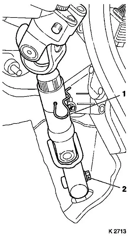
| 3. |
Detach steering intermediate shaft (1)
| • |
Remove lower clamp bolt (2)
|
| • |
Steering in straight ahead position
|
Important: Do not alter steering
wheel position.
|
| • |
Remove steering intermediate shaft
|
|
|
|
| 5. |
Detach front panelling
Note: On Tigra-B (Model
R97): detach front panelling
|
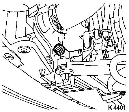
| 8. |
Remove lower engine compartment cover / splash protection
|
| 9. |
Drain coolant
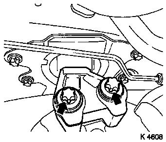
| • |
Place collecting basin underneath.
|
|
|
|
| 11. |
Remove air cleaner housing
|
| 12. |
Remove coolant compensation tank
|
| 13. |
Remove fuel filter (2)
| • |
Disconnect wiring harness plug (3)
|
|
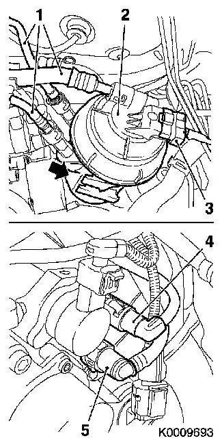
| 14. |
Remove fuel filter crash box
|
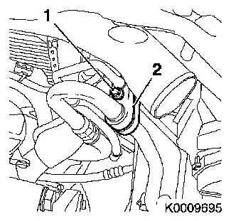
| 15. |
Detach brake servo vacuum line (5)
|
|
|
| 16. |
Detach 2 coolant hoses
|
| 17. |
Disconnect fan motor wiring harness
| • |
Disconnect 2 wiring harness plugs (1)
|
|
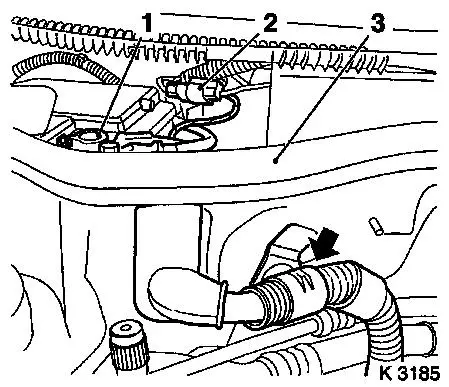
| 18. |
Disconnect wiring harness for engine management
| • |
Disconnect engine control unit wiring harness plug (2)
|
| • |
Disconnect wiring harness
|
|
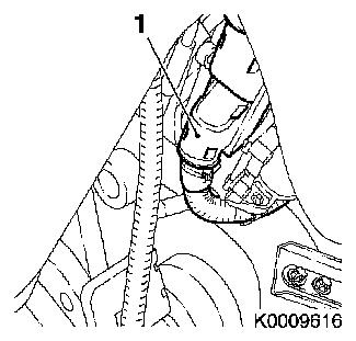
| 19. |
Detach ground cable
| • |
From side member
| – |
Remove castellated nut (arrow)
|
|
|
|

|
| 20. |
Disconnect starter/alternator wiring harness
| • |
Detach positive cable (1)
|
| • |
Disconnect central plug (2)
|
| • |
Unclip wiring harness from bracket (arrow)
|
|
|
|
| 21. |
Drain air conditioning system 
|
| 22. |
Disconnect refrigerant line of block connector (2)
|
|
|
| 24. |
Close coolant drain bolt
|
| 25. |
Release 2x axle shaft
| • |
Remove 2 cotter pins (1)
|
| • |
Unscrew 2 nuts (2)
| – |
Counterhold using KM-468-B
|
|
|
|
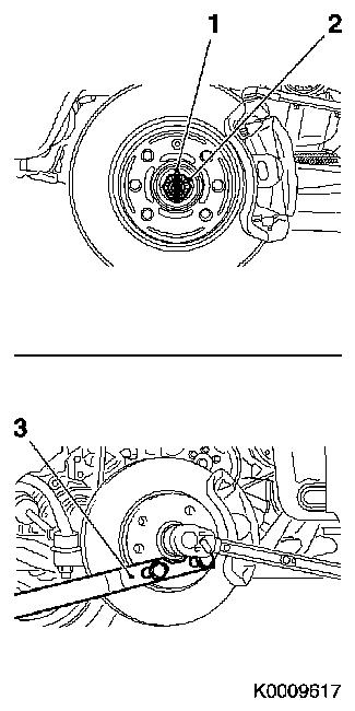
|
| 26. |
Detach 2x tie rod ball joints
|
|
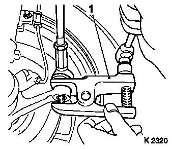
|
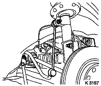
| 27. |
Detach 2x swing arm
| • |
From spring strut support tube
|
| • |
Unscrew 2 nuts
Note: Counterhold with
open-ended wrench
|
|
|
|
| 28. |
Detach 2 guide joints
|
|
|
| 29. |
Press out 2x axle shaft
|
| 31. |
Disconnect MTA transmission wiring harness plug (1)
| • |
Disconnect wiring harness
|
|
|
|
Important: When removing the
centre muffler, a catalytic converter, an exhaust manifold, or an
exhaust manifold with catalytic converter, secure that portion of
the exhaust system remaining on the vehicle against uncontrolled
suspension. The exhaust system piece with the flex pipe inside can
be secured for this purpose using suitable means, such as a wire on
the vehicle underbody. Bends in the flex pipe with an angle as
little as 5 – 10 degrees from the intended installation
position may result in damage with subsequent total failure of the
flex pipe.
|
| 32. |
Remove exhaust system
|
| 33. |
Remove exhaust system
| • |
Detach exhaust system
Note: 2nd mechanic
required.
|
|
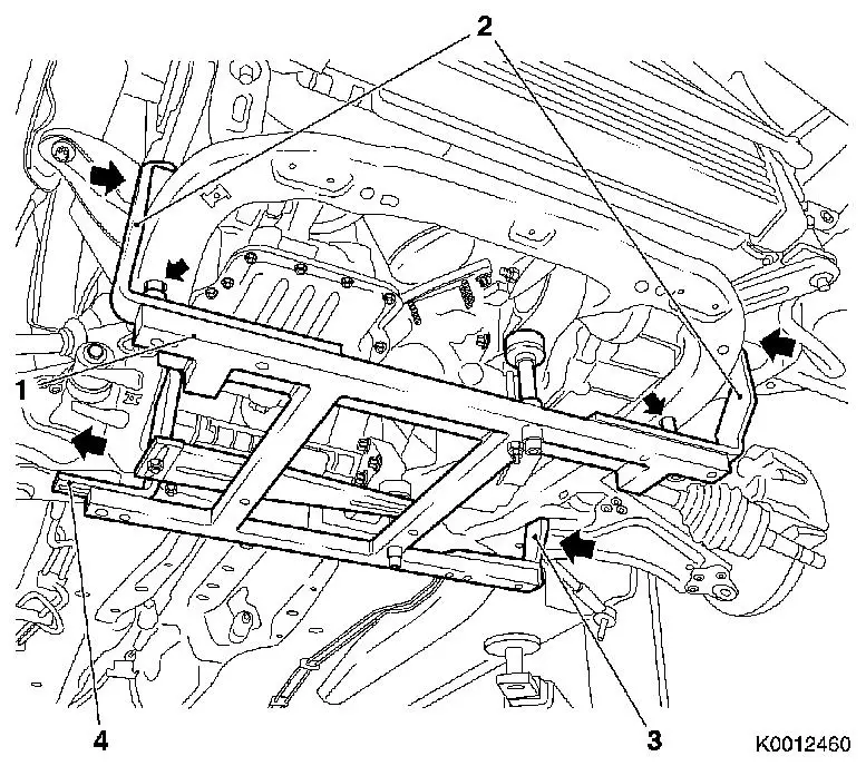
| 34. |
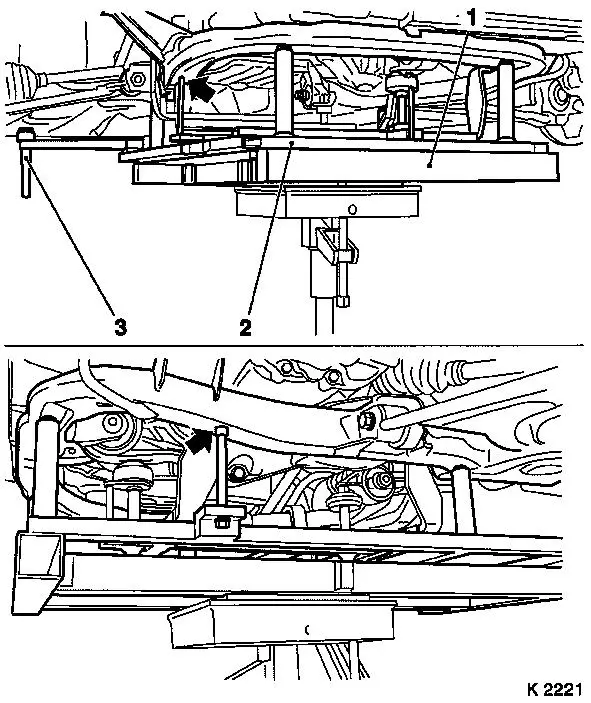
Attach KM-6394
| • |
Position KM-6394 (1) at the front on
the front axle body
Note: Both locating
pins (arrows) must be seated in the bores in the front axle
body.
|
| • |
Push front bracket (2) in the direction of the arrow
|
| • |
Place rear bracket (4), right hand side, on front axle body
|
| • |
Attach rear bracket (3), left hand side
|
|
|
|
|
| 35. |
Install support
| • |
On KM-6394
| – |
Adjust bracket (2) for support
|
|
|
| 36. |
Adjust 3x support
| • |
Transmission side
Note: Turn spindles
until mounts (3) are positioned at the guide journals free of
play.
|
| • |
Engine timing side
| – |
Insert journal of the support in the bore of the cylinder block
free of play (arrow)
|
|
|
|
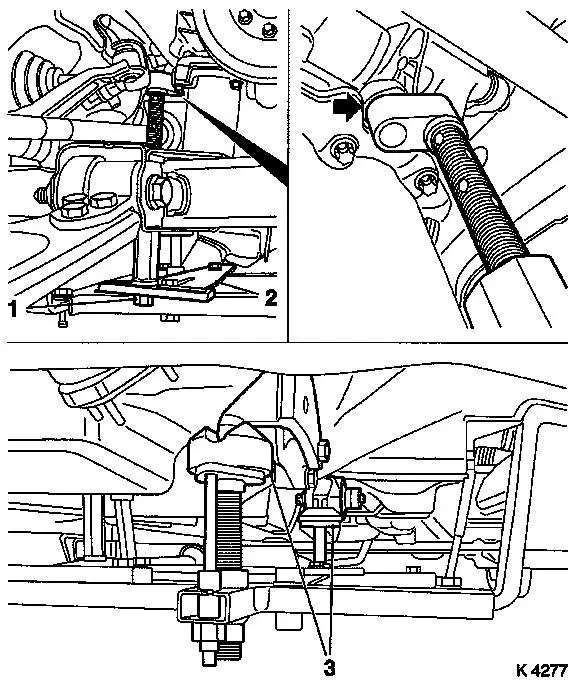
| 38. |
Detach right engine damping block
| • |
Loosen right engine bracket
|
|
|
|
| 39. |
Detach left engine damping block
| • |
Loosen left engine bracket
|
|
|
|
|
| 41. |
Insert hydraulic jack
|
| 42. |
Attach KM-6168 (2)
| • |
Position KM-6168
| – |
On KM-904 (1)
Note: Note differing
centring bolt diameters
|
|
| • |
Position KM-6168
| – |
Without play under front axle body
Note: Pay attention to
centring point in front axle body (arrows); lower body positioning
pins (3)
|
|
|
|
|
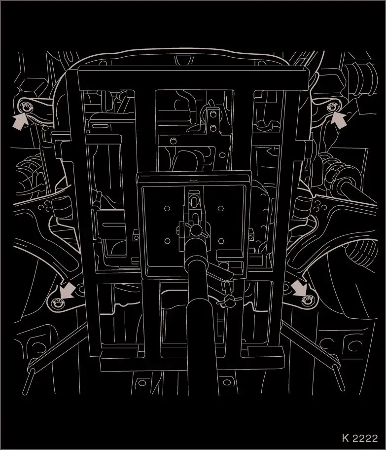
| 43. |
Release front axle body
Important: The removal of the
front axle body with an impulse or impact screwdriver is not
permitted
|
| • |
Unscrew 4 bolts (arrows)
|
|
|
Important: Carefully lower front
axle body with engine and transmission downwards out of engine
compartment. Do not damage attaching parts
|
| 44. |
Lower drive unit
Note: Second person
required
|
Important: Before installing the
front axle body, the lock nut threads must be checked for ease of
movement. Replace lock nuts if necessary
|
| 46. |
Check threads of 4 lock nuts
|
 Install
Important: Carefully guide the
front axle body with engine and transmission upwards into the
engine compartment. Guide the body positioning pins into body the
positioning holes. Do not damage attaching parts.
|
| 48. |
Raise drive unit
Note: Second person
required
|
| 49. |
Fasten front axle body
Important: Installation of the
front axle body with an impulse or impact screwdriver is not
permitted
|
| • |
Tighten 4 bolts 90 Nm + 45° +
15°
|
|
| 50. |
Remove hydraulic jack
|
| 52. |
Fasten left engine damping block
| • |
Tighten 2 new bolts 80 Nm + 60° -
75°
|
|
| 53. |
Fasten right engine damping block
| • |
Tighten 2 new bolts 60 Nm + 30° -
45°
|
|
| 57. |
Attach exhaust system
Note: Second person
required
|
| 58. |
Attach exhaust system
|
| 59. |
Connect MTA transmission wiring harness plug
|
| 60. |
Install lower engine compartment cover / splash protection
|
| 62. |
Attach front panelling
Note: On Tigra-B (Model
R97): attach front panelling
|
| 64. |
Attach 2x guide joint
| • |
Tighten 2 new bolts 60 Nm
|
|
| 65. |
Attach 2x swing arm
| • |
Tighten 2 new nuts 65 Nm
Note: Counterhold with
open-ended wrench
|
|
| 66. |
Attach 2 tie rods
| • |
Tighten 2 new nuts 35 Nm
|
|
| 67. |
Secure 2x axle shaft
| • |
Tighten 2 nuts 120 Nm
| – |
Counterhold using KM-468-B
|
|
| • |
Tighten 2 nuts 20 Nm + 90°
| – |
Counterhold using KM-468-B
|
|
| • |
Install 2 cotter pins
Note: If necessary,
unscrew the nut until a pin hole aligns with the next castle nut
groove
|
|
| 70. |
Fasten front wheels
| • |
Tighten 8x bolts 110 Nm
|
|
| 71. |
Connect refrigerant line block connector
|
| 72. |
Attach starter/alternator wiring harness
| • |
Route and secure wiring harness
|
|
| 73. |
Attach engine management wiring harness
| • |
Connect engine management wiring harness
|
|
| 74. |
Connect fan motor wiring harness
| • |
Connect 2 wiring harness plugs
|
|
| 75. |
Attach 2x coolant hose
|
| 76. |
Attach brake servo vacuum line
Note: Connection must
audibly engage
|
| 77. |
Install fuel filter crash box
|
| 78. |
Install fuel filter
| • |
Connect 2 wiring harness plugs
|
|
| 79. |
Install coolant compensation tank
|
| 80. |
Install air cleaner housing
|
| 81. |
Install steering intermediate shaft
Note: Wheels in
straight-ahead position
| • |
Push on steering intermediate shaft
Note: The bore for the
clamp bolt must be on the flat-milled side of the stub axle
|
| • |
Adjust length compensator
|
|
|
|
| 82. |
Fill air conditioning system
|
| 85. |
Program volatile memory
|
|
