|
J450100 Engine, Remove and Install (Y 17 DT, with
AC, LHD)
Note: KM-6394 must be used from model year 04 instead of
KM-6169-1 .
1. Open bonnet
2. Drain air conditioning
- Note! Drain air conditioning – see operation "Air
Conditioning, Drain " in group "D"
Caution!
On vehicles from model year 04 with ESP - the steering angle
sensor loses its basic adjustment each time the battery is
disconnected. It must be recalibrated.
3. Disconnect battery
|
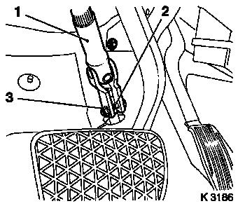
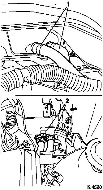
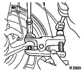
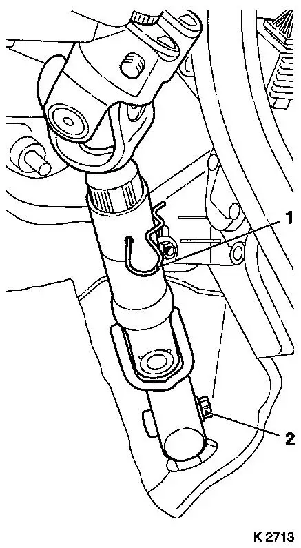
4. Remove steering intermediate shaft
(1)
- Remove lower clamp pin (2)
- Steering in straight ahead position
- Engage steering lock
- Remove steering intermediate shaft
- Caution! Do not change steering wheel position
|
|
5. Loosen front wheels
|
6. Release upper front panelling
|
|
7. Raise vehicle
|
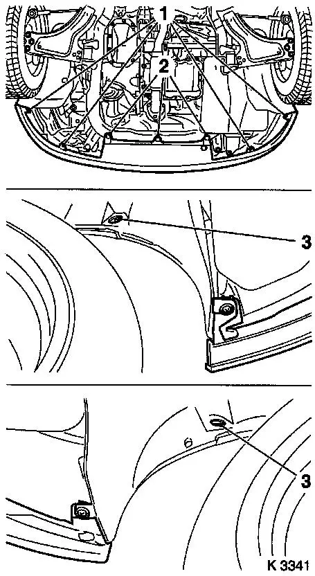
8. Release lower front panelling
- Disconnect wiring harness plug
- Remove 3 clips (2)
- Remove 4 bolts (1)
- Remove 2 nuts (3)
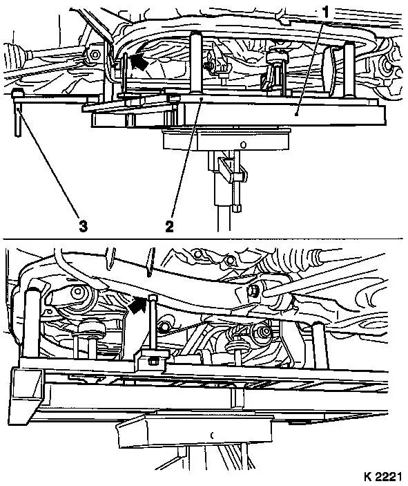
|
|
9. Detach front panelling
- Note! 2. mechanic
- Remove and close the hose – high-pressure –
Headlamp washer system
10. Remove front wheels
11. Remove horn
- Disconnect wiring harness plug
- Remove bolt
|
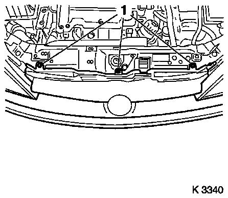
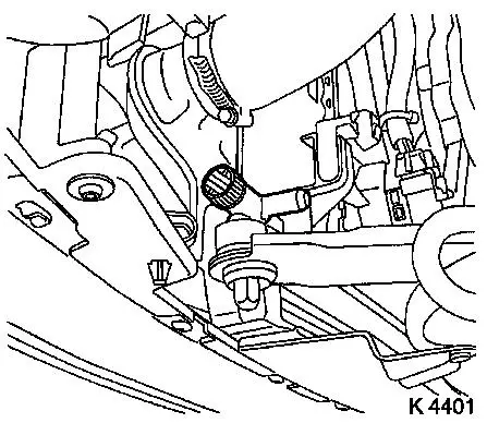
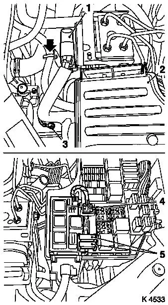
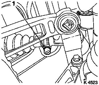
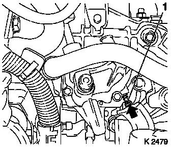
12. Remove ribbed V-belt cover
- Remove 3 bolts (1)
- Remove clip (arrow).
|
|
|
13. Drain coolant
- Place collecting basin underneath.
- Open drain bolt
|
|
14. Lower vehicle
|
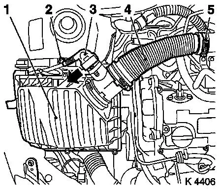
15. Remove air cleaner housing (1)
- Disconnect wiring harness plug for hot film mass air flow meter
(3)
- Release in direction of arrow
- Remove air intake hose (4)
- Remove bolt (2)
|
|
16. Remove coolant compensation
tank
- Unclip coolant hoses
- Detach coolant compensation tank and lay aside.
|
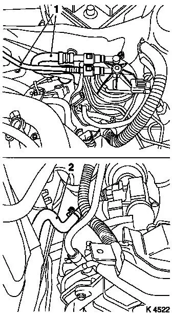
17. Detach heater fluid hoses
- From heater core (1)
- From auxiliary heater coolant line (2)
|
|
|
18. Remove wiring harness for engine
management
- Disconnect wiring harness plug
- Engine control unit, 2 combination plugs
- Unclip wiring harness and lay aside
|

|
|
19. Detach engine wiring harness
- Detach ground cable from battery.
- Detach battery positive cable
- Remove positive terminal (1)
- Disconnect combination plug (2)
- Remove rubber seal (3)
- Unclip wiring harness
- Remove cable harness and lay aside
|
|
|
20. Remove wiring harness for AC
- Detach wiring harness plug for ABS control unit (1)
- Release in direction of arrow
- Detach ground cable
- Remove relay box cover (2)
- Remove 2 fuses (5)
- Disconnect wiring harness plug (4)
- Release right relay frame and remove
- Unclip wiring harness and lay aside
|
|
|
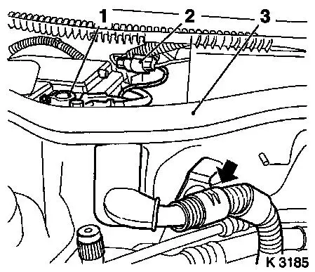
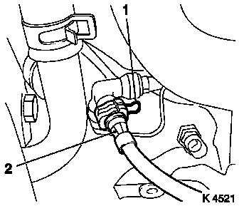
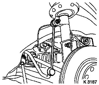
21. Detach pressure line for central
release (2)
- Remove cover of brake fluid reservoir
- Top up brake fluid reservoir to "MAX" marking
- Attach MKM-558-10
- Disengage retaining clip (1) with a screwdriver
- Suspend pressure line for central release
- Note! Escaping brake fluid
- Clamp retaining clip
|
|
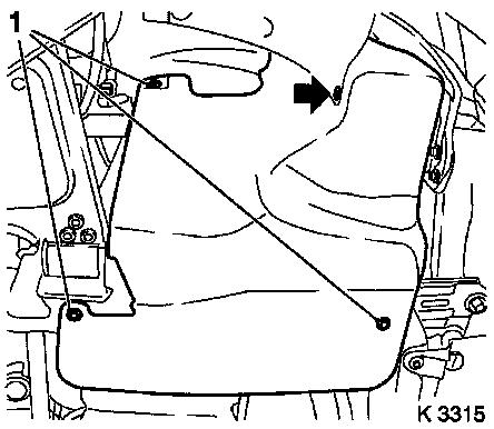
22. Detach brake servo vacuum line
- Detach vacuum line
- Withdraw vacuum line
- From bulkhead with grommet
|
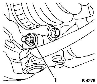
23. Detach fuel feed line (1)
- Detach using KM-796
- Unclip fuel line
- Close with KM-6015
|
|
24. Detach return fuel line (2)
|
25. Remove AC line
|
|
26. Raise vehicle
27. Close coolant drain bolt
|
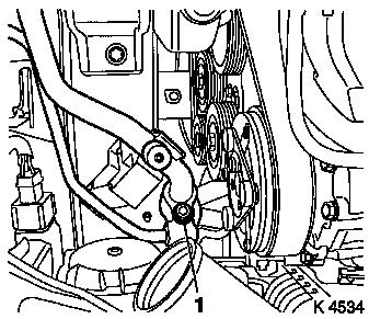
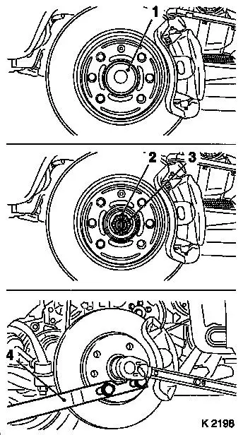
28. Loosen axle shafts
- Remove protective caps (1)
- Remove split pin (2)
- Attach KM-468-B (4)
- Unscrew nut (3)
- Hold with KM-468-B
- Remove washer
|
|
|
29. Detach tie rods
- From steering knuckle
- Remove 2 nuts
- Press off tie rods
|
|
|
30. Remove swing arm
- From spring strut support tube
- Remove 2 nuts
- Note! Counterhold using open-end spanner
|
|
|
31. Remove guide joints
- From steering knuckle
- Remove 2 nuts (1)
- Expand steering knuckle
|
|
32. Press out axle shafts
33. Raise vehicle
34. Detach exhaust system
Note: When removing
the centre muffler, a catalytic converter, an exhaust manifold, or
an exhaust manifold with catalytic converter, secure that portion
of the exhaust system remaining on the vehicle against uncontrolled
suspension.
For this purpose, the exhaust system portion including the flexpipe
may be fastened to the vehicle underbody using suitable means, e.g.
wire.
Caution!
Angular dislocations of the flexpipe as
small as 5 to 10 degrees offset from the intended installation
position can already cause damage and subsequent complete failure
of the flexpipe.
- Detach rear muffler
- Detach front exhaust pipe
35. Remove exhaust system
- Detach exhaust system
- Note! 2nd mechanic
|
36. Detach shift linkage
|
|
|
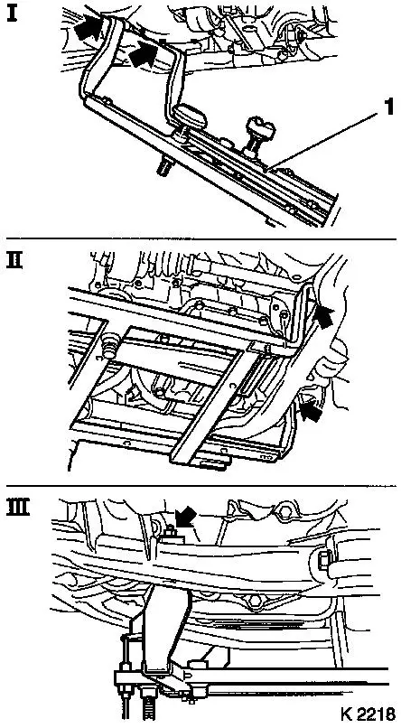
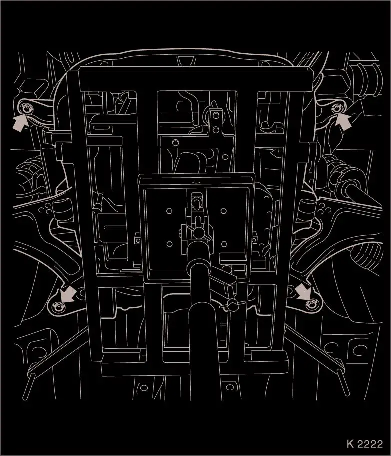
37. Attach KM-6169 (1)
- Place left of KM-6169 onto front axle body (arrows, illus.
I)
- Note! Guide pin must be seated in bore in front axle body
- Attach both right holders on the front axle body (arrows,
Illus. II).
- Note! Guide pin must be seated in bore in front axle body
(arrow, Illus. III)
- Tighten bolts
|
|
|
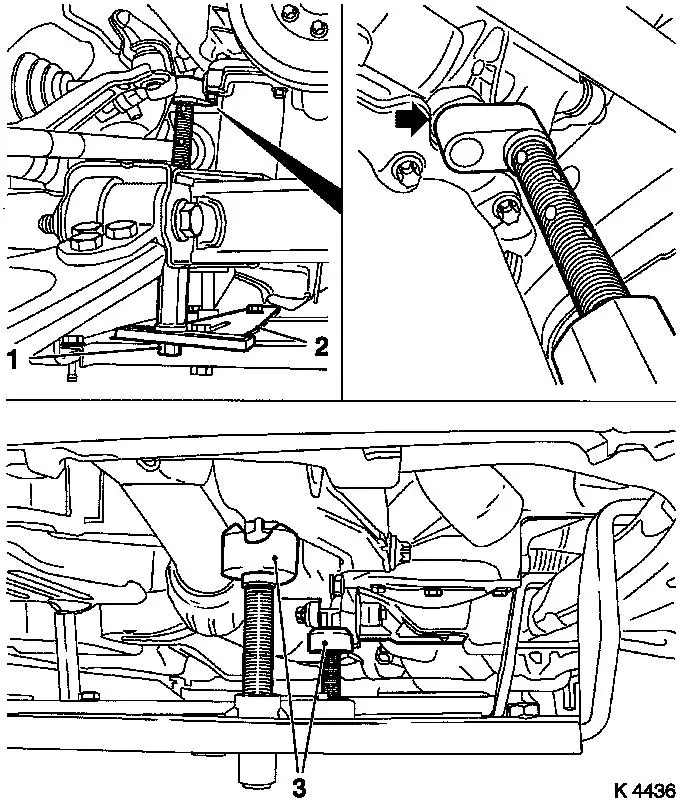
38. Install support
- To KM-6169
- Adjust bracket (2) for support
- Screw on nut (1)
|
|
39. Adjust supports
- Transmission side
- Note! Turn spindles until the mounts (3) are positioned at the
guide journals free of play
- Engine timing side
- Insert journal of the support in the bore of the cylinder block
without play (arrow)
- Tighten nuts (1)
40. Lower vehicle
|
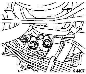
41. Remove right engine damping
block
|

|
|
42. Loosen left engine damping
block
- Loosen left engine bracket adapter
|
|
43. Raise vehicle
44. Insert hydraulic jack
|
45. Attach KM-6168 (2)
- Apply KM-6168
- On KM-904 (1)
- Note! Observe different centring bolt thread sizes
- Lower body positioning pins (3)
- Position KM-6168
- Without play under front axle body
- Note! Observe centring points in front axle body
|
|
46. Remove front axle body
- Remove 4 bolts
- Caution! Removal of the front axle body with an impulse or
impact screwdriver is not permissible
47. Lower drive unit
- Note! 2. mechanic
- Caution! Carefully lower engine with transmission downwards out
of engine compartment – do not damage attaching parts
48. Move out drive unit
|
49. Check thread of clamping nuts
- 4 off
- Caution! Before installing front axle body, the threads of the
clamping nuts must be checked for free movement, replace clamping
nuts if necessary
|
|
50. Replace AC seal rings
51. Insert drive unit
52. Raise drive unit
- Note! 2. mechanic
- Caution! Carefully guide engine with front axle body and
transmission upwards into the engine compartment. Note rear
centring tips. Do not damage attaching parts
- Steering shaft, upper radiator bracket
53. Fasten front axle body.
- Renew bolts
- Tighten bolts (90 Nm / 70 lbf. ft. + 45° + 15°.)
- Caution! Installation of the front axle body with an impulse or
impact screwdriver is not permissible
54. Remove hydraulic jack
55. Lower vehicle
56. Fasten left engine damping
block
- Tighten bolts (80 Nm / 59 lbf. ft. + 45° + 15°)
57. Install right engine damping
block
- To side member
- Tighten bolts (40 Nm / 29.5 lbf. ft.)
- On engine bracket
- Tighten bolts (60 Nm/44 lbf. ft + 30° + 15°.)
58. Raise vehicle
59. Detach support
60. Detach KM-6169
61. Install shift linkage.
62. Position exhaust system
63. Attach exhaust system
- Replace gasket
- Replace nuts
- Tighten nuts (65 Nm / 48 lbf. ft.)
- Install damping rings
- Attach rear muffler
64. Lower vehicle
65. Install axle shafts
66. Attach guide joints
- Replace nuts
- Tighten bolts (60 Nm / 44.5 lbf. ft.)
67. Attach pendulum
- Replace nuts
- Tighten nuts (65 Nm / 48 lbf. ft.)
- Note! Counterhold using open-end spanner
68. Attach tie rods
- Replace nuts
- Tighten nuts (60 Nm / 44 lbf. ft.)
69. Attach axle shafts
- Replace nuts
- Attach KM-468-B
- Tighten nuts (120 Nm / 89 lbf. ft.)
- Loosen nuts
- Tighten nuts (20 Nm / 15 lbf. ft. + 90°)
- Install retaining split pins
- Note! If necessary, turn nut back until one split pin hole
aligns with the next castellated nut groove
- Install protective caps
70. Install ribbed V-belt cover
- Screw in bolts
- Install clip
71. Install horn
- Tighten bolts
- Connect wiring harness plug.
72. Position front panelling
- Note! 2. mechanic
- Install high-pressure headlamp washer hose
73. Fasten lower front panelling
- Install clips
- Tighten bolts
- Tighten nuts
- Connect wiring harness plug.
74. Attach front wheels
75. Lower vehicle
76. Fasten upper front panelling
77. Fasten front wheels
- Tighten bolts (110 Nm / 81 lbf. ft.)
78. Attach AC line
- Tighten bolt (20 Nm / 15 lbf. ft.)
- Note! Check sealing ring installation positions
79. Install brake servo vacuum line
- Route vacuum line
- through bulkhead with grommet
- Insert in brake servo
- Close water deflector service flap
80. Attach return fuel line
81. Attach fuel feed line
82. Attach pressure line for central
release
- Note! Pressure line must engage audibly
- Detach MKM-558-10
- Bleed hydraulic clutch actuation – see operation
"Hydraulic Clutch Actuation, Bleed " in group "K".
- Screw on cover of brake fluid reservoir
83. Attach wiring harness for AC
- Attach wiring harness
- Install right relay frame
- Connect combination plug
- Insert fuse
- Install relay frame cover
- Connect ground cable.
- Attach wiring harness plug for ABS control unit
84. Attach engine wiring harness
- Route wiring harness
- Connect wiring harness plug.
- Install positive terminal
- Attach positive cable
- Connect ground cable.
- Fasten cable harness
- Install rubber seal
85. Attach wiring harness for engine
management
- Route wiring harness
- Connect wiring harness plug.
- Attach wiring harness
86. Connect heater fluid hoses
87. Install coolant compensation tank
88. Install air cleaner housing
- Tighten bolt
- Fasten air intake hose.
- Tighten clamp (3.5 Nm / 2.6 lbf. ft.)
- Connect wiring harness plug to hot film mass air flow
meter
|
89. Install steering intermediate
shaft
- Note! Wheels in straight ahead position
- Release steering lock
- Push on steering intermediate shaft
- Note! Bore hole for clamp bolt must be on the flat milled side
of the steering pivot
- Insert clamp pin
- Replace nut (2)
- Adjust length compensator
- Tighten nut (22 Nm/16 lbf. ft.)
- Remove KM-6181
|
|
|
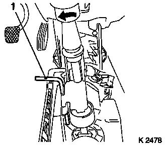
90. Lock transmission shift linkage
- Unclip manual shift lever cover
- Arrest shift lever and shift lever housing
- Engage locking pin in adjustment bore in shift cover by turning
shift rod to the left (direction of 3rd gear) (arrow)
|
|
91. Raise vehicle
92. Fasten clamp
- Tighten bolt (12 Nm / 9 lbf. ft + 90°+ 90° to 90°+
90° + 45°)
93. Lower vehicle
|
94. Check transmission shift
linkage
- Remove Adjusting Pin KM-527-A
- Note! Locking pin (1) in adjustment bore releases automatically
when first shifting towards "R"
- Engage all gears
- Clip in manual shift lever cover
|
|
95. Connect battery
96. Calibrate steering angle sensor
Note: Rotate the
steering wheel one time from its right-hand to its left-hand
stop.
97. Top up coolant
- Note! Top up and bleed cooling system – see operation
"Cooling System, Top up and Bleed".
- Observe specified coolant quantity
98. Charge air conditioning
- Note! Charge air conditioning – see operation "Air
Conditioning, Evacuate and Charge" in group "D"
99. Program volatile memories
100. Close bonnet
|
