|
J330100 All Pistons with Con-rod, Remove and
Install (Z 18 XE, with Air Conditioning, LHD)
Note: KM-6394 must be used as of model year 04 instead of
KM-6169-1 .
Note: The customer
should be informed of the choice between ECOService and
ECOService-Flex before the oil change.
 Remove Remove
| 2. |
Disconnect battery
Note: In vehicles from
model year 04 onwards with ESP - the steering angle sensor loses
its basic adjustment each time the battery is disconnected and must
be recalibrated.
|
| 3. |
Remove engine cover.
| • |
Unscrew oil filler pipe cap
|
| • |
Screw on oil filler pipe cap
|
|
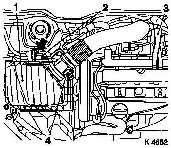
| 4. |
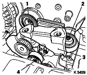
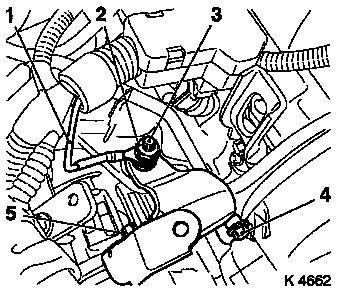
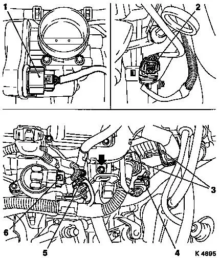
Remove air cleaner housing (1)
| • |
Disconnect 2 wiring harness plugs
| – |
Hot film mass air flow meter (4), tank vent valve (2)
|
|
| • |
Detach engine vent hose (3)
|
|
|
|
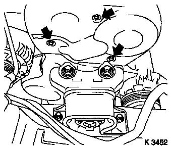
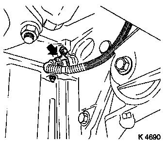
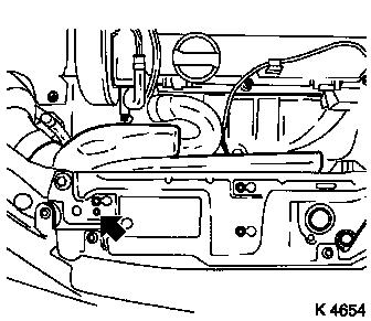
| 5. |
Remove upper part of toothed belt cover
| • |
Unscrew 3 bolts (arrows)
|
| • |
Unclip from rear toothed belt cover
|
|
|
|
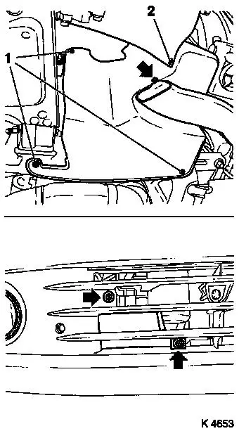
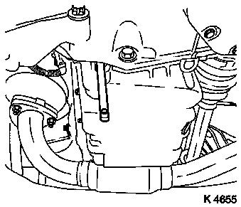
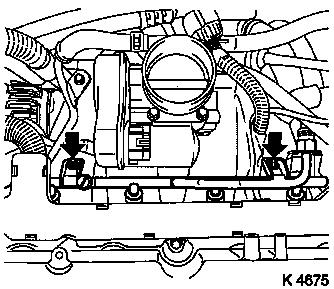
| 7. |
Remove right-hand air duct
| • |
Unscrew 3 bolts (arrows)
|
|
| 8. |
Remove ribbed V-belt cover
|
|
|
| 10. |
Detach front right wheel
|
| 12. |
Remove right front wheel.
|
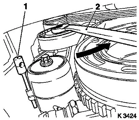
| 14. |
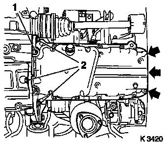
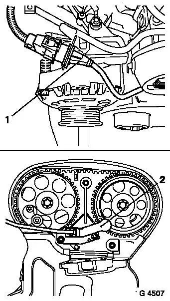
Remove ribbed V-belt
| • |
Tension ribbed V-belt tensioner in direction of arrow with
KM-913-A (2)
|
|
|
|
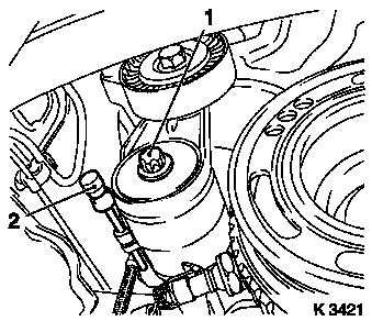
| 15. |
Remove ribbed V-belt tensioner
| • |
Tension ribbed V-belt tensioner.
|
| • |
Release ribbed V-belt tensioner
|
|
|
|
| 16. |
Detach crankshaft ribbed V-belt pulley
| • |
Prise front closure plug out of oil pan
|
|
|
|
| 17. |
Release lower part of toothed belt cover
| • |
Unclip from rear toothed belt cover
|
|
|
|
| 19. |
Loosen exhaust system
Note: Bends in the flex
pipe with an angle as little as 5 – 10 degrees from the
intended installation position may result in damage with subsequent
total failure of the flex pipe.
| • |
When removing the centre muffler, a catalytic converter, an
exhaust manifold or an exhaust manifold with catalytic converter,
the exhaust system piece remaining in the vehicle must be prevented
from swinging uncontrollably.
Note: The exhaust
system piece with the flex pipe inside can be secured for this
purpose using suitable means, such as a wire on the vehicle
underbody.
|
| • |
Remove wiring harness plug for catalytic converter control
oxygen sensor
|
| • |
Suspend front exhaust pipe from left front axle body
|
|
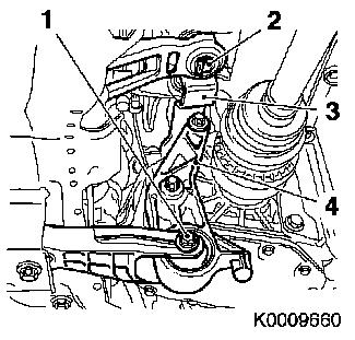
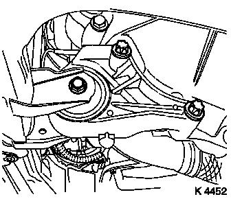
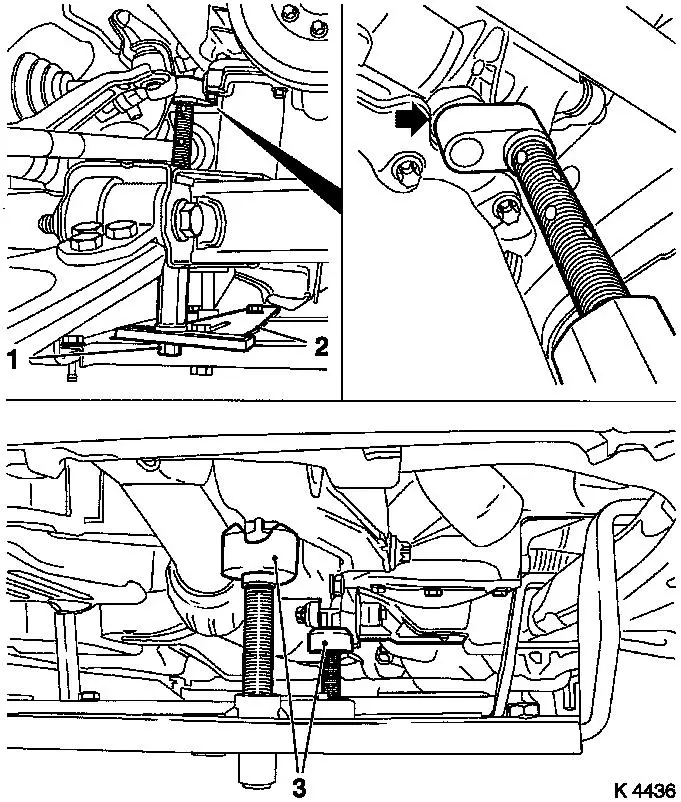
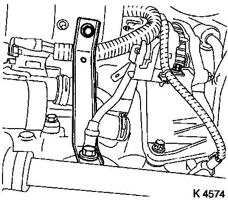
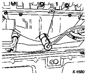
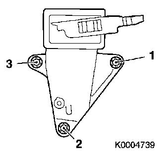
| 20. |
Release shift guide (3)
| • |
Remove retaining clip (2)
|
|
| 21. |
Release rear reaction member (4)
|
|
|
| 22. |
Remove front reaction member
|
|
|
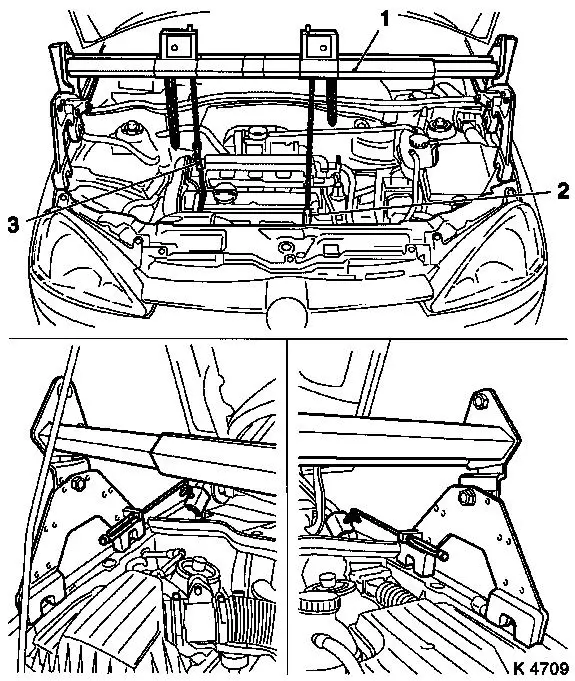
| 24. |
Use MKM-883-1 (1)
Note: Second person
required
|
| 25. |
Fasten MKM-883-1
Note: Observe
manufacturer's instructions
|
| 26. |
Attach engine
| • |
To right engine transport shackle (3)
|
| • |
To front left engine transport shackle (2)
Note: The front left
engine transport shackle is used only to stabilise the engine
|
|
|
|
| 27. |
Detach right engine damping block
|
| 28. |
Lift engine
| • |
Carefully raise the engine approx. 40 mm on the timing side
with MKM-883-1
Note: Observe
manufacturer's instructions
|
|
|
|
| 30. |
Remove oil pan
| • |
Lever out rear sealing plug (1)
|
| • |
Oil pump
| – |
Unscrew 3 bolts (arrows)
|
|
|
|
|
| 32. |
Lower engine
Note: When lowering pay
attention to the shift guide and rear reaction member
|
| 34. |
Fasten rear reaction member
|
| 35. |
Install front reaction member
| • |
Tighten bolted connection 60 Nm
|
|
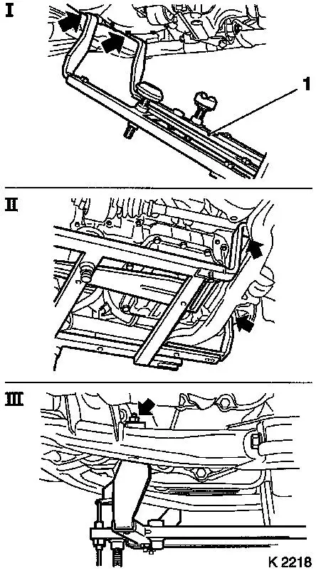
| 36. |
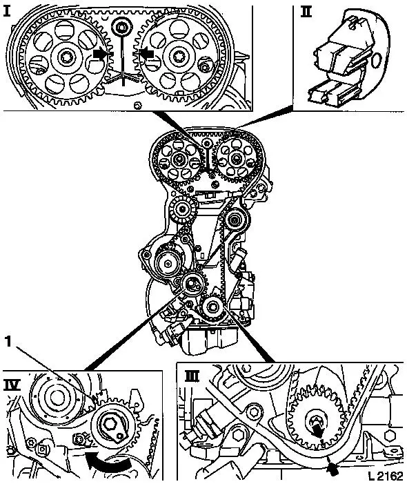
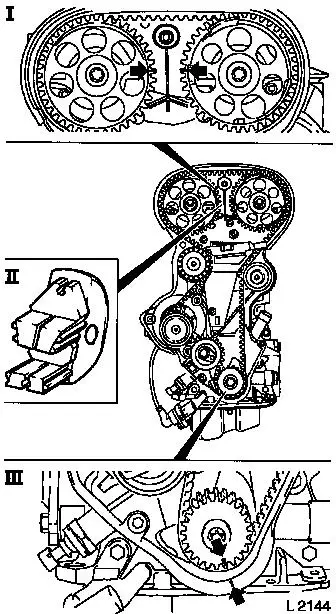
Attach KM-6169 (1)
| • |
Attach KM-6169 to left of front axle
body (arrows, illus. I)
Note: Guide pin must be
seated in bore in front axle body
|
| • |
Attach both right holders on the front axle body (arrows,
Illus. II).
Note: Guide pin must be
seated in bore in front axle body (arrow, Fig. III)
|
|
|
|
| 37. |
Install support to KM-6169
| • |
Adjust bracket (2) for support
|
|
| 38. |
Adjust supports
| • |
Transmission side
| – |
Turn spindles until mounts (3) are positioned at guide journals
free of play
|
|
| • |
Engine timing side
| – |
Insert journal of the support in the bore of the cylinder block
without play (arrow)
|
|
|
|
|
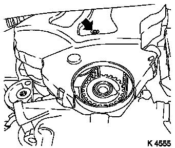
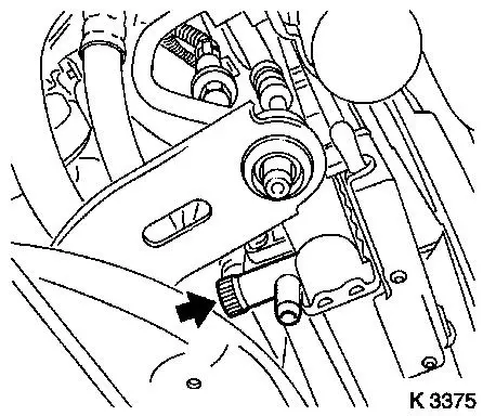
| 40. |
Drain coolant
| • |
Place collecting basin underneath.
|
| • |
Open drain bolt (arrow)
|
|
| 43. |
Remove MKM-883-1
Note: Second person
required
|
|
|
| 44. |
Remove right engine damping block
| • |
Loosen engine bracket adapter
|
|
|
|
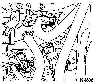
| 45. |
Remove preheater line for throttle valve module
| • |
Disconnect wiring harness plug for coolant temperature
sensor
|
|
| 46. |
Remove upper part of toothed belt cover
| • |
Unclip from rear toothed belt cover
|
|
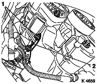
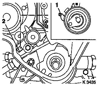
| 47. |
Remove camshaft sensor (2)
| • |
Disconnect wiring harness plug (1)
|
|
| 48. |
Remove lower part of toothed belt cover
| • |
Unclip from rear toothed belt cover
|
|
|
|
| 49. |
Set 1st cylinder to TDC of combustion stroke
| • |
Install crankshaft V-belt pulley bolt
|
| • |
Set crankshaft to mark.
| – |
Marks on drive gear toothed belt and rear toothed belt cover
must align (III).
|
|
| • |
Fix camshaft sprockets in position.
| – |
Marks must be opposite one another and aligned with the top
edge of the cylinder head (I)
|
|
|
| 50. |
Remove toothed belt
Note: Mark running
direction.
| • |
Release toothed belt tension roller (IV)
| – |
Turn adjusting eccentric in direction of arrow (clockwise)
until pointer (1) of the toothed belt tension roller is located
just before left stop.
|
|
|
|
|
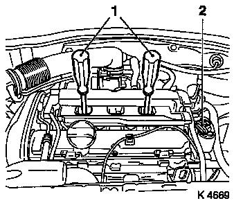
| 51. |
Remove ignition module
| • |
Disconnect wiring harness plug (2)
|
| • |
Extract using KM-6009 (1)
Note: Do not tilt
|
|
| 52. |
Remove cylinder head cover
| • |
Detach engine vent hose
|
| • |
Unclip wiring harness of mixture regulation heated oxygen
sensor
|
|
|
|
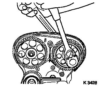
| 53. |
Remove camshaft sprockets
| • |
Unscrew 2 bolts
| – |
Counterhold camshafts at hexagonal section
|
|
|
|
|
| 54. |
Remove exhaust side toothed belt guide roller
|
| 55. |
Remove intake side toothed belt guide roller
|
| 56. |
Remove right engine bracket (3)
|
| 57. |
Remove toothed belt tension roller
|
| 59. |
Remove toothed belt drive pulley
| • |
Unscrew crankshaft ribbed V-belt pulley bolt
|
|
| 60. |
Release rear toothed belt cover
|
|
|
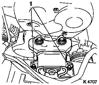
| 61. |
Release alternator
| • |
Release alternator support
| – |
Unscrew 2 upper bolts (1)
|
|
|
|
|
| 62. |
Detach intake manifold support
|
|
|
| 63. |
Remove wiring harness for engine management
| • |
Disconnect 2 wiring harness plugs
| – |
Oil pressure switch (1), crankshaft sensor (arrow)
|
|
|
|
|
| 65. |
Remove rear of toothed belt cover
|
| 66. |
Pull fuel evaporation hose from throttle valve module
|
|
|
| 67. |
Remove alternator shackle
| • |
Remove ground cable (1)
|
| • |
Unscrew 2x bolts (4, 5)
|
| • |
Swing alternator backwards.
|
|
|
|
Important: Observe safety
precautions and national regulations
|
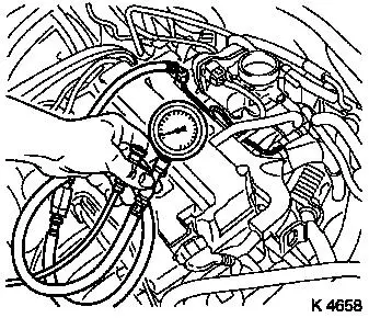
| 68. |
Release fuel pressure with KM-J-34730-91 on fuel distributor pipe
| • |
Unscrew test connection protective cap
|
|
|
|
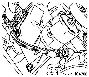
| 69. |
Detach fuel line (1) from fuel distributor pipe
|
|
|
| 70. |
Remove wiring harness for engine management
| • |
Disconnect 7x wiring harness plugs
| – |
Throttle valve module (1), engine control unit (3), knock
sensor (4), combination plug (5), EGR valve (6), mixture regulation
oxygen sensor (2)
|
|
| • |
Remove wiring trough
| – |
Unscrew from engine transport shackle (arrow)
|
|
| • |
Set wiring harness to one side
|
|
|
|
| 71. |
Remove fuel distributor pipe
| • |
Unscrew 2x bolt (arrows)
|
| • |
Pull out fuel distributor pipe with injectors and engine
management wiring harness
|
|
| 72. |
Detach preheater return hose for throttle valve module from
throttle valve module
|
| 73. |
Detach heating return hose from intake manifold
|
| 74. |
Remove right rear engine transport shackle
|
|
|
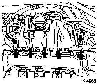
| 75. |
Remove intake manifold
| • |
Unscrew 7x nuts (arrows)
|
| • |
Remove brake servo vacuum line
|
|
|
|
| 77. |
Detach centre coolant hose from coolant pump connection,
coolant flange
|
| 78. |
Detach upper radiator hose from thermostat housing
|
|
|
| 79. |
Remove intake pipe
| • |
Pull intake pipe out of bracket
|
|
|
|
| 80. |
Remove heated oxygen sensor for mixture regulation
| • |
Screw out carefully using KM-6129
(1)
|
|
| 81. |
Remove exhaust manifold heat shield
|
| 82. |
Detach oil dipstick guide tube
| • |
Swivel the oil dipstick guide tube to one side
|
|
|
|
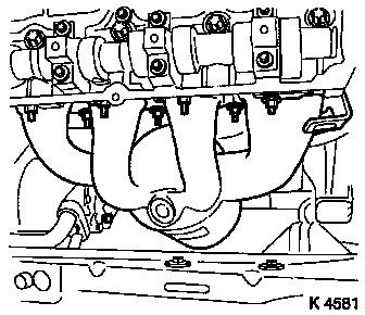
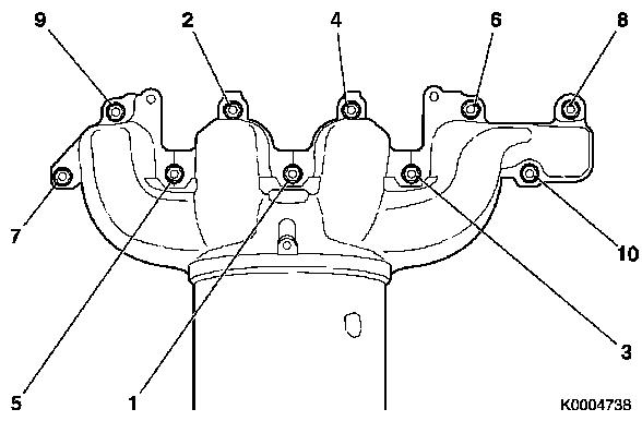
| 83. |
Remove exhaust manifold
| • |
Unscrew 10x nut
| – |
Remove engine transport shackle
|
|
|
|
|
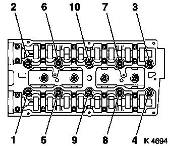
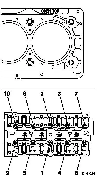
| 84. |
Remove cylinder head bolts
Note: Undo bolts in
order shown
| • |
Unscrew 10 bolts
| – |
Loosen 10x bolts (90 °)
|
| – |
Loosen 10x bolts (180 °)
|
|
|
| 85. |
Remove cylinder head
Note: Second person
required
| • |
Place cylinder head on wooden blocks
|
| • |
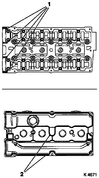
Remove cylinder head gasket
|
|
|
|
| 87. |
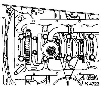
Remove con-rod bearing cap (1)
Note: Observe cylinder
sequence
| • |
Mark con-rods with con-rod bearing caps
|
| • |
Unscrew 4 bolts
Note: The mating
surfaces of the cod-rods and con-rod bearing caps form an
individual fit and must not be damaged or interchanged. Do not lay
on mating surfaces.
|
| • |
Push piston with con-rod upwards
|
|
| 91. |
Rotate crankshaft in direction of engine rotation
(180°)
|
|
|
| 92. |
Remove con-rod bearing cap (1)
Note: Observe cylinder
sequence
| • |
Mark con-rods with con-rod bearing caps
|
| • |
Unscrew 4 bolts
Note: The mating
surfaces of the cod-rods and con-rod bearing caps form an
individual fit and must not be damaged or interchanged. Do not lay
on mating surfaces.
|
| • |
Push piston with con-rod upwards
|
|
| 95. |
Remove con-rod bearing shells
Note: Note sequence
| • |
Mark con-rod bearing shells
|
|
 Install
| 96. |
Inspect crank drive components
|
| 97. |
Insert con-rod bearing shells into con-rods and con-rod bearing
caps
|
| 98. |
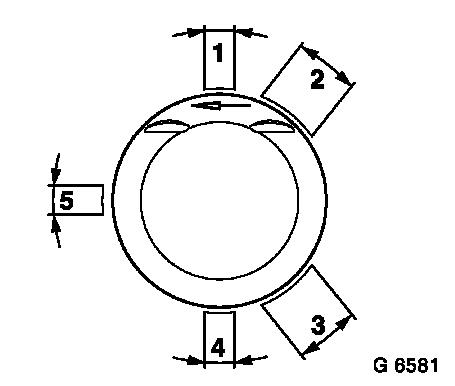
Adjust piston ring gaps
| • |
Turn piston rings
| – |
Upper rings in position (1)
|
| – |
Middle rings in position (4)
|
|
| • |
Turn oil scraper ring
| – |
Intermediate ring in position (5)
|
| – |
Steel band rings in position (2) or (3)
|
|
|
|
|
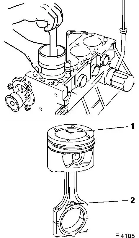
| 99. |
Install piston
Note: Arrow (1) on
bottom of piston points to engine timing side. Bead (2) on con-rod
should face transmission side
| • |
Coat piston and cylinder bores with engine oil
|
| • |
Compress piston rings with piston ring tensioner
|
|
| 101. |
Attach con-rod bearing cap
Note: Bead on con-rod
bearing cap should face transmission side
| • |
Coat con-rod journal with engine oil
|
| • |
Tighten 4x bolts 25 Nm + 30°
|
|
|
|
| 102. |
Rotate crankshaft in direction of engine rotation
(180°)
|
| 104. |
Install piston
Note: Arrow (1) on
bottom of piston points to engine timing side. Bead (2) on con-rod
should face transmission side
| • |
Coat piston and cylinder bores with engine oil
|
| • |
Compress piston rings with piston ring tensioner
|
|
| 106. |
Attach con-rod bearing cap
Note: Bead on con-rod
bearing cap should face transmission side
| • |
Coat con-rod journal with engine oil
|
| • |
Tighten 4x bolts 25 Nm + 30°
|
|
| 108. |
Clean sealing surfaces
| • |
Cylinder block, crankshaft bearing bridge, oil pan, cylinder
head, timing case, exhaust manifold, oil filter housing, thermostat
housing, cylinder head cover
|
|
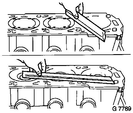
| 109. |
Check for plane surface
| • |
Cylinder head, cylinder block
|
| • |
With straightedge, feeler gauge
|
|
|
|
| 110. |
Attach cylinder head
| • |
Attach cylinder head gasket
| – |
OBEN/TOP mark must point upwards.
|
|
|
| 111. |
Install cylinder head bolts
Note: Note tightening
sequence.
| • |
Tighten 10x bolts 25 Nm + 90° +
90° + 90° + 45°
|
|
|
|
|
| 112. |
Install exhaust manifold
| • |
Position engine transport shackle
|
| • |
Tighten 10x nuts 12 Nm + 12 Nm
Note: The nuts must be
tightened in two stages in accordance with the tightening
sequence
| – |
Note tightening sequence.
|
|
| • |
Attach bracket for engine control unit wiring harness
|
|
|
| 113. |
Fasten oil dipstick guide tube
|
| 114. |
Install exhaust manifold heat shield
|
| 115. |
Install oxygen sensor, mixture regulation, heated
| • |
Apply assembly paste (white) to thread
|
| • |
Tighten oxygen sensor 30 Nm
|
|
| 117. |
Attach upper radiator hose
|
| 118. |
Attach centre coolant hose
|
| 120. |
Install intake manifold
| • |
Attach brake servo vacuum line
| – |
Connection must audibly engage
|
|
|
| 121. |
Install right rear engine transport shackle
|
| 122. |
Attach heating return hose
|
| 123. |
Attach preheater hose for throttle valve module
|
| 124. |
Install fuel distributor pipe
| • |
Replace 4x injector seal rings
|
| • |
Connect fuel distributor pipe with injectors and engine
management wiring harness
|
|
| 125. |
Attach wiring harness for engine management
| • |
Connect 7x wiring harness plugs
|
| • |
Attach ground cable with bracket for knock sensor wiring
harness plug
|
|
| 127. |
Attach fuel evaporation hose
|
| 128. |
Install alternator shackle
|
| 129. |
Install rear toothed belt cover
|
| 130. |
Install toothed belt drive pulley
|
| 131. |
Install toothed belt tension roller
| • |
Detent lever (1) of toothed belt tension roller must engage in
guide web (2) of oil pump.
|
| • |
Bolt in bolt
Note: Adjust toothed
belt tension before tightening bolt.
|
|
|
|
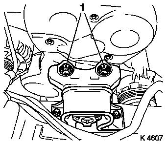
| 132. |
Install right engine bracket
| • |
Insert bolts with locking compound (red)
|
| • |
Tighten bolts 65 Nm + 45° -
60°
Note: Note tightening
sequence (1 - 3).
|
|
|
|
| 133. |
Install intake side toothed belt guide roller
Note: The toothed belt
guide roller with the greater diameter is installed at the intake
side.
|
| 134. |
Install exhaust side toothed belt guide roller
|
| 135. |
Install 2x camshaft sprockets
Note: Second person
required
| • |
Tighten 2x bolts 50 Nm + 60° +
15°
| – |
Counterhold camshafts at hexagonal section
|
|
|
| 136. |
Fix camshaft sprockets in position.
| • |
Marks must be opposite one another and aligned with the top
edge of the cylinder head (I)
|
| • |
Use KM-852 (II)
| – |
Turn the camshafts at hexagonal section
|
|
|
| 137. |
Lock crankshaft
| • |
Install crankshaft V-belt pulley bolt
|
| • |
Set crankshaft to mark.
| – |
Marks on drive gear toothed belt and rear toothed belt cover
must align (III).
|
|
|
|
|
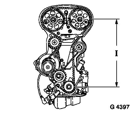
| 138. |
Install toothed belt
Note: Note running
direction
| • |
Position toothed belt
Note: Tensioned side
must be taut (I)
|
|
|
|
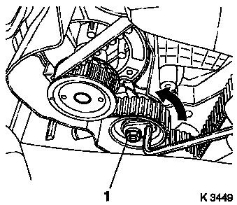
| 139. |
Tension toothed belt
| • |
Tension toothed belt tension roller
| – |
Turn adjusting eccentric in direction of arrow (anticlockwise)
until pointer of the toothed belt tension roller is located just
before left stop
|
|
| • |
Fasten toothed belt tension roller bolt (1)
|
|
|
|
| 141. |
Timing, Check
| • |
Turn crankshaft in direction of engine rotation at the
crankshaft ribbed V-belt pulley bolt (720°)
|
| • |
Set crankshaft to mark.
| – |
Marks on drive gear toothed belt and rear toothed belt cover
must align (III).
|
|
| • |
Use KM-852 (II)
| – |
Marks must be opposite one another and aligned with the top
edge of the cylinder head (I)
|
|
|
|
|
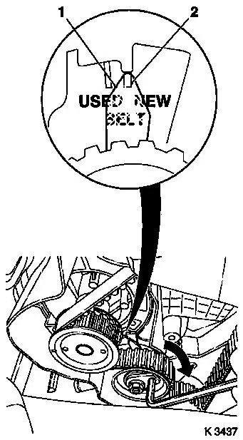
| 143. |
Adjust toothed belt tension
| • |
Release toothed belt tension roller
|
| • |
Turn adjustment eccentric in direction of arrow (clockwise)
until tension roller toothed belt pointer (1) is aligned with notch
mark (2).
| – |
Adjust used toothed belts to the marking USED
|
| – |
Adjust new toothed belts to the marking NEW
|
|
| • |
Tighten toothed belt tension roller bolt 20 Nm
|
|
| 144. |
Check toothed belt tension
| • |
Pointer on the toothed belt tension roller and notch mark must
align.
| – |
Adjust used toothed belts to the marking USED
|
| – |
Adjust new toothed belts to the marking NEW
|
|
|
|
|
| 145. |
Install lower part of toothed belt cover
| • |
Clip to rear of toothed belt cover
|
|
| 146. |
Install camshaft sensor
| • |
Insert bolts with locking compound
|
|
| 147. |
Install upper part of toothed belt cover
| • |
Clip to rear of toothed belt cover
|
|
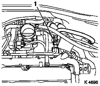
| 148. |
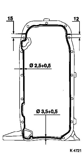
Install cylinder head cover
| • |
Apply sealant (1)
Note: Complete assembly
operations within 10 minutes
|
| • |
Attach engine vent hose
|
| • |
Clip in cable for mixture regulation heated oxygen sensor
|
|
|
|
| 149. |
Install ignition module
|
| 150. |
Install preheater line for throttle valve module
|
| 151. |
Connect coolant temperature sensor wiring harness plug
|
| 152. |
Connect camshaft sensor wiring harness plug
|
| 153. |
Use MKM-883-1
Note: Second person
required
|
| 154. |
Fasten MKM-883-1
Note: Observe
manufacturer's instructions
|
| 155. |
Attach engine
| • |
To right engine transport shackle
|
| • |
To front left engine transport shackle
Note: The front left
engine transport shackle is used only to stabilise the engine
|
|
| 159. |
Release rear reaction member
|
| 160. |
Remove front reaction member
|
| 162. |
Lift engine
Note: Observe
manufacturer's instructions
| • |
Carefully raise the engine approx. 40 mm on the timing side
with MKM-883-1
|
|
| 164. |
Install oil pan
| • |
Apply sealant
Note: Complete assembly
operations within 10 minutes
|
| • |
At cylinder block
| – |
Tighten 12x bolts 10 Nm
|
|
| • |
Insert rear closure plug
|
|
|
|
| 166. |
Lower engine
Note: When lowering pay
attention to the shift guide and rear reaction member
|
| 168. |
Fasten rear reaction member
|
| 169. |
Install front reaction member
| • |
Tighten bolted connection 60 Nm
|
|
| 170. |
Attach exhaust system
|
| 171. |
Attach wiring harness for engine management
| • |
Connect 2 wiring harness plugs
|
|
| 172. |
Attach KM-6169
| • |
Position KM-6169 on the left on the
front axle body
| – |
Guide pin must be seated in bore in front axle body
|
|
| • |
Attach both right holders on the front axle body
| – |
Guide pin must be seated in bore in front axle body
|
|
|
| 173. |
Install support to KM-6169
| • |
Adjust mount for support
|
|
| 174. |
Adjust supports
| • |
Transmission side
| – |
Turn spindles until mounts are positioned at guide journals
free of play
|
|
| • |
Engine timing side
| – |
Insert journal of the support in the bore of the cylinder block
free of play
|
|
|
| 176. |
Clean thread on cylinder head.
|
| 177. |
Install right engine damping block
| • |
Fasten engine bracket adapter
| – |
Tighten bolts 60 Nm + 30° -
45°
|
|
| • |
Fasten engine damping block
|
|
| 180. |
Remove MKM-883-1
Note: Second person
required
|
| 185. |
Fasten alternator
| • |
Fasten alternator support
|
|
| 186. |
Attach intake manifold support
|
| 187. |
Install ribbed V-belt tensioner
| • |
Tension ribbed V-belt tensioner with KM-913-A
|
|
| 188. |
Attach crankshaft ribbed V-belt pulley
| • |
Tighten bolt 95 Nm + 30° +
15°
|
| • |
Insert front closure plug
|
|
| 189. |
Install ribbed V-belt
Note: Observe running
direction and installation position
| • |
Slacken ribbed V-belt tensioner with KM-913-A
|
|
| 190. |
Install ribbed V-belt cover
|
| 191. |
Install right-hand air duct
|
| 193. |
Attach front right wheel
|
| 195. |
Fasten right front wheel.
|
| 196. |
Install air cleaner housing
| • |
Attach engine vent hose
|
| • |
Clip in tank vent valve
|
| • |
Connect 2 wiring harness plugs
|
|
| 197. |
Install engine cover.
| • |
Unscrew oil filler pipe cap
|
| • |
Screw on oil filler pipe cap
|
|
| 199. |
Calibrate steering angle sensor
| • |
Rotate the steering wheel one time from its right-hand to its
left-hand stop
|
|
| 200. |
Program volatile memories
|
| 201. |
Top up engine oil
| • |
Start engine and allow to run until oil pressure telltale
extinguishes.
|
| • |
Check engine oil level, if necessary correct.
|
|
| 202. |
Top up and bleed cooling system 
|
| 203. |
Reset service interval using TECH 2
Note: If the customer
decides to have ECOService - connect TECH2 and reprogram engine
control unit
|
| 204. |
Fill out the service sticker
|
|
