|
J314570 Both Camshafts, Remove and Install (Z 18
XE, with Air Conditioning, LHD)
 Remove Remove
| 2. |
Disconnect battery
Note: In vehicles from
model year 04 onwards with ESP - the steering angle sensor loses
its basic adjustment each time the battery is disconnected and must
be recalibrated.
|
| 3. |
Remove engine cover.
| • |
Unscrew oil filler pipe cap
|
| • |
Screw on oil filler pipe cap
|
|
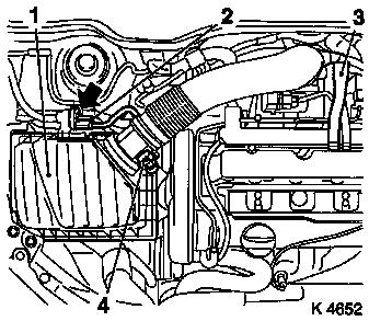
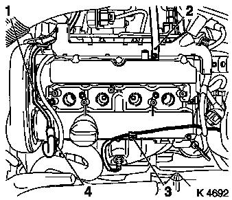
| 4. |
Remove air cleaner housing (1)
| • |
Disconnect 2 wiring harness plugs
| – |
Hot film mass air flow meter (4), tank vent valve (2)
|
|
| • |
Detach engine vent hose (3)
|
|
|
|
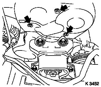
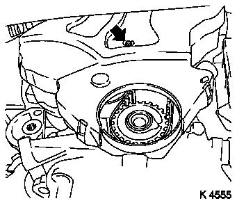
| 5. |
Remove upper part of toothed belt cover
| • |
Unscrew 3 bolts (arrows)
|
| • |
Unclip from rear toothed belt cover
|
|
|
|
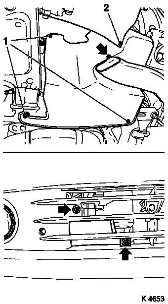
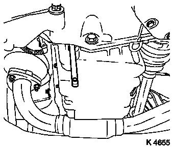
| 7. |
Remove right-hand air duct
| • |
Unscrew 3 bolts (arrows)
|
|
| 8. |
Remove ribbed V-belt cover
|
|
|
| 10. |
Detach front right wheel
|
| 12. |
Remove right front wheel.
|
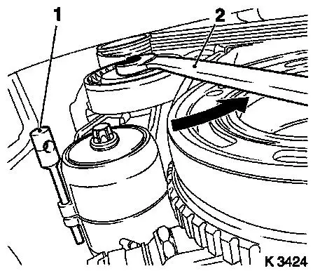
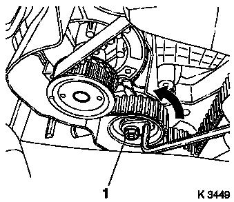
| 14. |
Remove ribbed V-belt
| • |
Tension ribbed V-belt tensioner in direction of arrow with
KM-913-A (2)
|
|
|
|
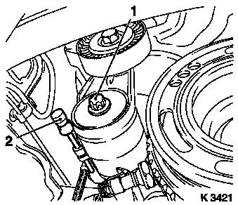
| 15. |
Remove ribbed V-belt tensioner
| • |
Tension ribbed V-belt tensioner.
|
| • |
Release ribbed V-belt tensioner
|
|
|
|
| 16. |
Detach crankshaft ribbed V-belt pulley
| • |
Prise front closure plug out of oil pan
|
|
|
|
| 17. |
Release lower part of toothed belt cover
| • |
Unclip from rear toothed belt cover
|
|
|
|
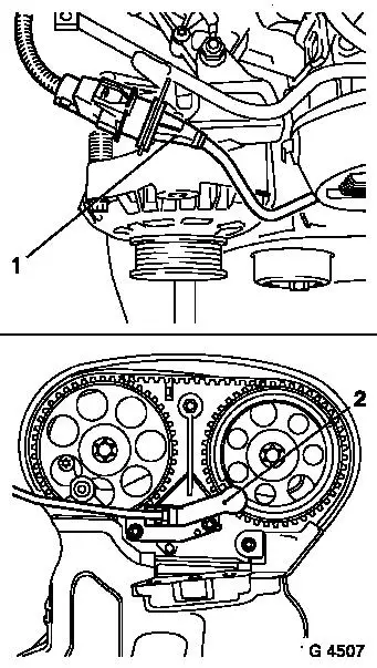
| 20. |
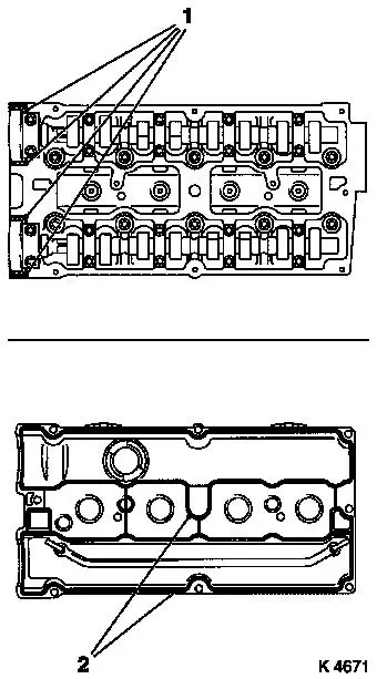
Disconnect camshaft sensor wiring harness plug (1)
|
| 21. |
Remove lower part of toothed belt cover
| • |
Unclip from rear toothed belt cover
|
|
| 22. |
Remove camshaft sensor (2)
|
|
|
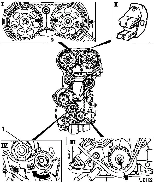
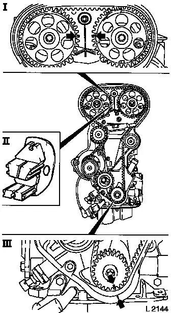
| 23. |
Set 1st cylinder to TDC of combustion stroke
| • |
Install crankshaft V-belt pulley bolt
|
| • |
Set crankshaft to mark.
| – |
Marks on drive gear toothed belt and rear toothed belt cover
must align (III).
|
|
| • |
Fix camshaft sprockets in position.
| – |
Marks must be opposite one another and aligned with the top
edge of the cylinder head (I)
|
|
|
| 24. |
Remove toothed belt
| • |
Release toothed belt tension roller (IV)
| – |
Turn adjusting eccentric in direction of arrow (clockwise)
until pointer (1) of the toothed belt tension roller is located
just before left stop.
|
|
|
|
|
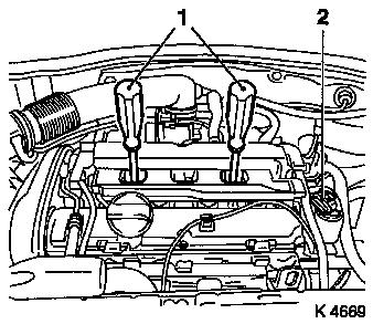
| 25. |
Remove ignition module
| • |
Disconnect wiring harness plug (2)
|
| • |
Extract using KM-6009 (1)
Note: Do not tilt
|
|
|
|
| 26. |
Release preheater line - throttle valve module (1)
| • |
Disconnect coolant temperature sensor wiring harness plug
(4)
|
| • |
Unclip wiring harness of mixture regulation heated oxygen
sensor (3)
|
|
| 27. |
Remove cylinder head cover
| • |
Detach engine vent hose (2)
|
|
|
|
| 29. |
Remove exhaust camshaft sprocket
| • |
Remove bolt
| – |
Counterhold camshaft at hexagonal section
|
|
|
| 30. |
Remove intake camshaft sprocket
| • |
Remove bolt
| – |
Counterhold camshaft at hexagonal section
|
|
|
| 31. |
Release rear toothed belt cover
|
|
|
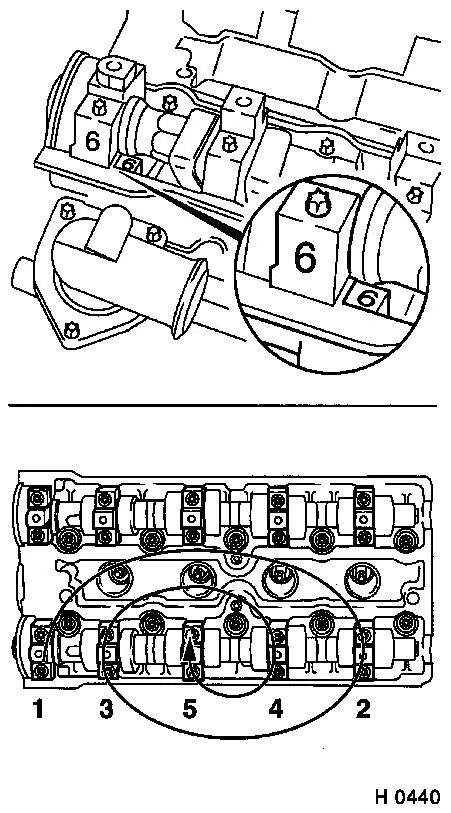
| 32. |
Remove exhaust camshaft
| • |
Remove camshaft bearing cap
Note: Note
identification
|
| • |
Release camshaft bearing caps in stages, working in a spiral
pattern from the outside inwards
Note: Camshaft must be
evenly released from the bearing seats
|
| • |
Remove camshaft seal ring
|
|
| 33. |
Remove intake camshaft
| • |
Remove camshaft bearing cap
Note: Note
identification
|
| • |
Release camshaft bearing caps in stages, working in a spiral
pattern from the outside inwards
Note: Camshaft must be
evenly released from the bearing seats
|
| • |
Remove camshaft seal ring
|
|
|
|
| 34. |
Inspect components
| • |
Camshafts, camshaft bearing caps, cylinder head, ribbed V-belt,
ribbed V-belt tensioner, ribbed V-belt pulleys, toothed belt
drive
|
|
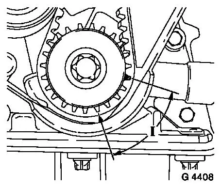
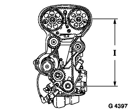
| 35. |
Position crankshaft
| • |
Set crankshaft to 60° before no.1 cylinder TDC (dimension
I).
|
|
|
|
 Install
| 36. |
Install intake camshaft
| • |
Coat sliding surfaces with engine oil
|
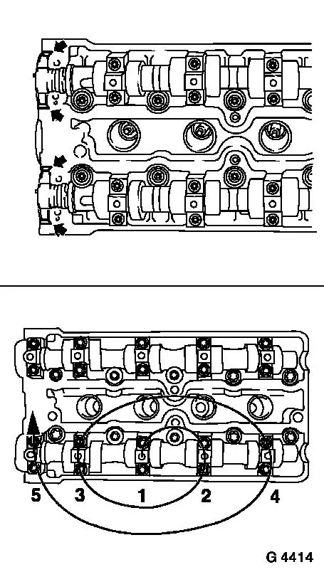
| • |
Apply sealant in the area of the camshaft seal ring
(arrows)
Note: Do not apply
sealant in vicinity of oil channels. Complete installation work
within 10 minutes.
|
| • |
Insert camshaft, camshaft bearing cap
Note: Observe
identification and allocation
|
| • |
Tighten 10x bolts for camshaft bearing caps 8 Nm
| – |
Tighten in stages, working in a spiral pattern from the inside
outwards
|
|
|
| 37. |
Install exhaust camshaft
| • |
Coat sliding surfaces with engine oil
|
| • |
Apply sealant in the area of the camshaft seal ring
(arrows)
Note: Do not apply
sealant in vicinity of oil channels. Complete installation work
within 10 minutes.
|
| • |
Insert camshaft, camshaft bearing cap
Note: Observe
identification and allocation
|
| • |
Tighten 10x bolts for camshaft bearing caps 8 Nm
| – |
Tighten in stages, working in a spiral pattern from the inside
outwards
|
|
|
|
|
| 38. |
Install exhaust camshaft seal ring
| • |
Coat seal lip with grease
|
| • |
Place seal ring on camshaft journal
|
| • |
Pull in camshaft seal ring with KM-422 , bolt and camshaft sprocket washer (2)
|
|
| 39. |
Install intake camshaft seal ring
| • |
Coat seal lip with grease
|
| • |
Place seal ring on camshaft journal
|
| • |
Pull in camshaft seal ring with KM-422 , bolt and camshaft sprocket washer (2)
|
|
|
|
| 40. |
Fasten rear toothed belt cover
|
| 41. |
Install camshaft sprocket on exhaust side
Note: Attach camshaft
sprocket with cylinder recognition to exhaust camshaft.
| • |
Attach KM-6347 , KM-956-1
|
| • |
Tighten bolt 50 Nm + 60° +
15°
Note: Second person
required
|
| • |
Remove KM-6347 , KM-956-1
|
|
| 42. |
Install camshaft sprocket on the intake side
Note: Attach camshaft
sprocket with cylinder recognition to exhaust camshaft.
| • |
Attach KM-6347 , KM-956-1
|
| • |
Tighten bolt 50 Nm + 60° +
15°
Note: Second person
required
|
| • |
Remove KM-6347 , KM-956-1
|
|
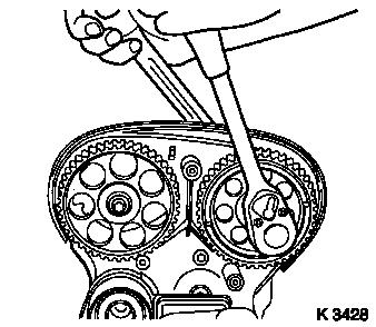
| 43. |
Fix camshaft sprockets in position.
| • |
Marks must be opposite one another and aligned with the top
edge of the cylinder head.
|
| • |
Use KM-852
| – |
Turn the camshafts at hexagonal section
|
|
|
| 44. |
Put toothed belt in place
| • |
Position toothed belt
Note: Tensioned side
(I) must be taut.
|
|
|
|
| 45. |
Tension toothed belt
| • |
Tension toothed belt tension roller
| – |
Turn adjusting eccentric in direction of arrow (anticlockwise)
until pointer of the toothed belt tension roller is located just
before left stop
|
|
| • |
Fasten toothed belt tension roller bolt (1)
|
|
|
|
| 47. |
Timing, Check
| • |
Turn crankshaft in direction of engine rotation at the
crankshaft ribbed V-belt pulley bolt (720°)
|
| • |
Set crankshaft to mark.
| – |
Marks on drive gear toothed belt and rear toothed belt cover
must align (III).
|
|
| • |
Use KM-852 (II)
| – |
Marks must be opposite one another and aligned with the top
edge of the cylinder head (I)
|
|
|
|
|
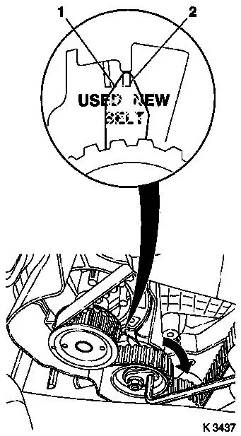
| 49. |
Adjust toothed belt tension
| • |
Release toothed belt tension roller
|
| • |
Turn adjustment eccentric in the direction of the arrow
(clockwise) until pointer (1) of toothed belt tension roller is
aligned with the appropriate notch mark
| – |
Adjust used toothed belts to the marking USED
|
| – |
Adjust new toothed belts to the marking NEW (2)
|
|
| • |
Tighten toothed belt tension roller bolt 20 Nm
|
|
| 50. |
Check toothed belt tension
| • |
Pointer on the toothed belt tension roller and notch mark must
align.
| – |
Adjust used toothed belts to the marking USED
|
| – |
Adjust new toothed belts to the marking NEW
|
|
|
| 51. |
Clean threads
| • |
Camshaft sensor to cylinder head
|
|
|
|
| 53. |
Install camshaft sensor
| • |
Insert bolts with locking compound (red)
|
|
| 54. |
Install lower part of toothed belt cover
| • |
Clip to rear of toothed belt cover
|
|
| 55. |
Install upper part of toothed belt cover
| • |
Clip to rear of toothed belt cover
|
|
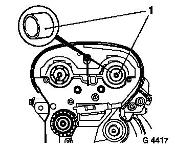
| 56. |
Install cylinder head cover
| • |
Apply sealant (1)
Note: Complete assembly
operations within 10 minutes
|
| • |
Attach engine vent hose
|
|
| 57. |
Fasten preheater line - throttle valve module
| • |
Connect coolant temperature sensor wiring harness plug
|
| • |
Clip in wiring harness of mixture regulation heated oxygen
sensor
|
|
| 58. |
Connect wiring harness plug from camshaft sensor
|
|
|
| 59. |
Install ignition module
| • |
Connect wiring harness plug
|
|
| 61. |
Install ribbed V-belt tensioner
| • |
Tighten bolt (35 Nm / 26 lbf. ft.)
|
| • |
Tension ribbed V-belt tensioner with KM-913-A
|
|
| 62. |
Attach crankshaft ribbed V-belt pulley
| • |
Tighten bolt 95 Nm + 30° +
15°
|
| • |
Insert front closure plug
|
|
| 63. |
Install ribbed V-belt
Note: Observe running
direction and installation position
| • |
Slacken ribbed V-belt tensioner with KM-913-A
|
|
| 64. |
Install ribbed V-belt cover
|
| 65. |
Install right-hand air duct
|
| 67. |
Attach front right wheel
|
| 69. |
Fasten right front wheel.
|
| 70. |
Install air cleaner housing
| • |
Attach engine vent hose
|
| • |
Clip in tank vent valve
|
| • |
Connect 2 wiring harness plugs
|
|
| 71. |
Install engine cover.
| • |
Unscrew oil filler pipe cap
|
| • |
Screw on oil filler pipe cap
|
|
| 73. |
Calibrate steering angle sensor
| • |
Rotate the steering wheel one time from its right-hand to its
left-hand stop
|
|
| 74. |
Program volatile memories
|
|
