|
Replace front camshaft sealing ring (Z 14 XE, Z 16
YNG with air conditioning, RHD)
Important: On vehicles as of
model year 04 with ESP - the steering angle sensor loses its basic
adjustment each time the battery is disconnected. It must be
recalibrated.
|
| 2. |
Disconnect battery
|
| 3. |
Remove engine cover.
| • |
Unscrew oil filler pipe cap
|
| • |
Screw on oil filler pipe cap
|
|
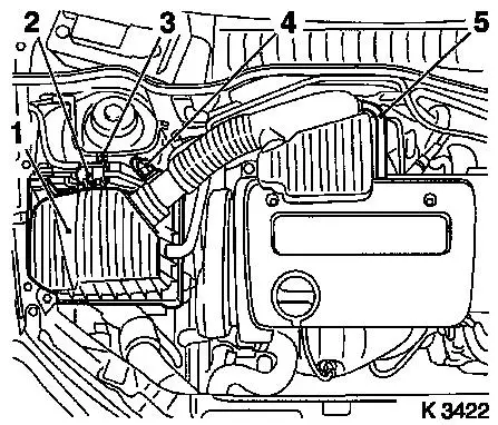
| 4. |
Remove air cleaner housing (1)
| • |
Disconnect wiring harness plug
| – |
Intake air temperature sensor (4), tank vent valve (2)
|
|
| • |
Detach engine vent hose (5)
|
|
|
|
| 5. |
Loosen right front wheel.
|
| 7. |
Remove right front wheel.
|
| 9. |
Remove ribbed V-belt cover
|
|
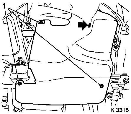
|
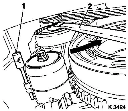
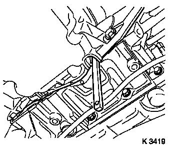
| 10. |
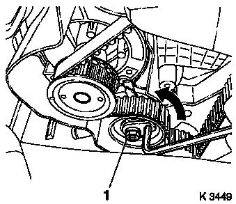
Remove ribbed V-belt
| • |
Tension ribbed V-belt tensioner in direction of arrow
| – |
Using KM-913-A (2) (SW 15)
|
|
| • |
Mark running direction.
|
|
|
|
| 11. |
Remove ribbed V-belt tensioner
| • |
Tension ribbed V-belt tensioner.
|
| • |
Release ribbed V-belt tensioner
|
|
|
|
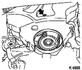
| 12. |
Detach crankshaft ribbed V-belt pulley
| • |
Lever out front closure plug
|
|
|
|
| 13. |
Release lower part of toothed belt cover
| • |
Unclip from rear toothed belt cover
|
|
|
|
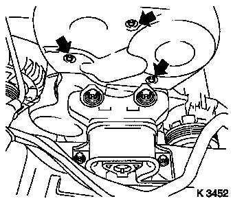
| 15. |
Remove upper part of toothed belt cover
| • |
Remove 3 bolts (arrows)
|
| • |
Unclip from rear toothed belt cover
|
|
|
|
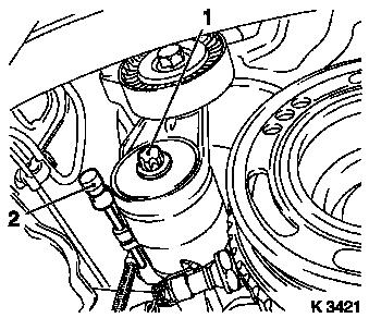
| 16. |
Remove camshaft sensor (1)
| • |
Disconnect wiring harness plug
|
|
|
|
| 17. |
Remove lower part of toothed belt cover
| • |
Unclip from rear toothed belt cover
|
|
|
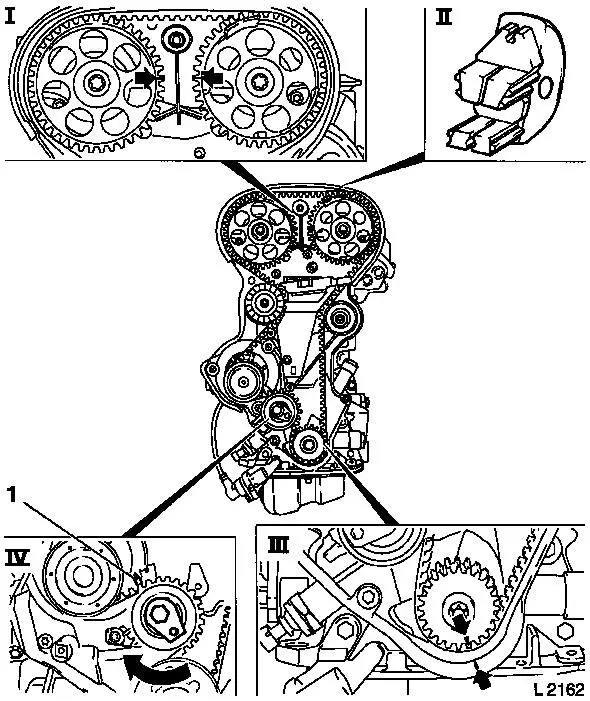
| 18. |
Set 1st cylinder to TDC of combustion stroke
| • |
Install crankshaft V-belt pulley bolt
|
| • |
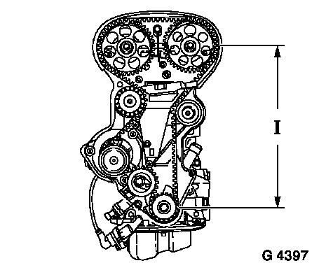
Set crankshaft to mark.
| – |
Turn crankshaft evenly
Note: Marks on drive
gear toothed belt and rear toothed belt cover must align (III).
|
|
| • |
Fix camshaft sprockets in position.
Note: Marks must be
opposite one another and aligned with the top edge of the cylinder
head (I)
|
|
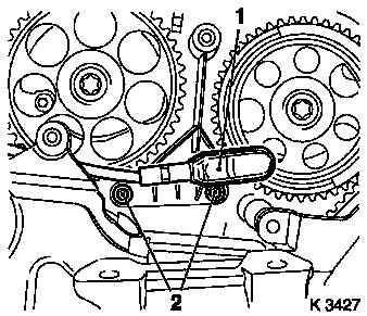
| 19. |
Remove toothed belt
| • |
Release toothed belt tension roller (IV)
| – |
Turn adjusting eccentric in direction of arrow (clockwise)
until pointer (1) of the toothed belt tension roller is located
just before left stop.
|
|
|
|
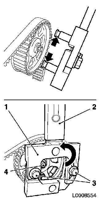
| 21. |
Remove camshaft sprocket on exhaust side
| • |
Use KM-6347 (1), KM-956-1 (2)
|
| • |
Attach KM-6347 , KM-956-1
Note: Loosen the
clamping screws (3) of KM-6347 and insert
KM-6347 connected to KM-956-1 in the camshaft sprocket. The notches on
KM-6347 must engage in the camshaft
sprocket (arrows). Ensure that it engages properly. Rotate KM-6347 in the direction of the arrow using
KM-956-1 .
| – |
Tighten 2 clamping screws
|
|
| • |
Loosen camshaft sprocket bolt (4)
|
| • |
Remove KM-6347 , KM-956-1
| – |
Loosen 2 clamping screws
|
|
| • |
Unscrew camshaft sprocket bolt
|
|
|
|
| 22. |
Remove camshaft sprocket on intake side
| • |
Attach KM-6347 , KM-956-1
Note: Loosen the
clamping screws of KM-6347 and insert
KM-6347 connected to KM-956-1 in the camshaft sprocket. The notches on
KM-6347 must engage in the camshaft
sprocket. Ensure that it engages properly. Rotate KM-6347 in the direction of the arrow using KM-956-1 .
| – |
Tighten 2 clamping screws
|
|
| • |
Loosen camshaft sprocket bolt
|
| • |
Remove KM-6347 , KM-956-1
| – |
Loosen 2 clamping screws
|
|
| • |
Unscrew camshaft sprocket bolt
|
|
| 23. |
Release rear toothed belt cover
|
| 24. |
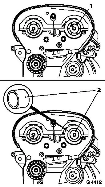
Remove exhaust camshaft seal ring
| • |
Carefully prise out seal ring (1)
|
|
| 25. |
Clean sealing surface
|
| 26. |
Inspect components
| • |
Camshafts, ribbed V-belt, ribbed V-belt tensioner, ribbed
V-belt pulleys, toothed belt drive
|
|
| 27. |
Install exhaust camshaft seal ring
| • |
Coat seal lip with grease
|
| • |
Place seal ring on camshaft journal
|
| • |
Install camshaft seal ring
| – |
With KM-422 (2), bolt and camshaft
sprocket washer
|
|
|
|
|
| 28. |
Fasten rear toothed belt cover
|
| 29. |
Install camshaft sprocket on exhaust side
Note: Attach camshaft
sprocket with cylinder recognition to exhaust camshaft.
| • |
Replace bolt
Note: 2. Fitter
required
| – |
Attach KM-6347 , KM-956-1
|
|
| • |
Tighten bolt
| – |
Tightening torque 50 Nm + 60° +
15°
|
|
| • |
Remove KM-6347 , KM-956-1
|
|
| 30. |
Install camshaft sprocket on the intake side
| • |
Replace bolt
Note: 2. Fitter
required
| – |
Attach KM-6347 , KM-956-1
|
|
| • |
Tighten bolt
| – |
Tightening torque 50 Nm + 60° +
15°
|
|
| • |
Remove KM-6347 , KM-956-1
|
|
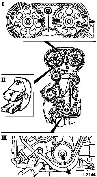
| 31. |
Fix camshaft sprockets in position.
Note: Marks must be
opposite one another and aligned with the top edge of the cylinder
head (I)
| • |
Use KM-852 (II)
| – |
Turn the camshafts at hexagonal section
|
|
|
| 32. |
Check that 1st cylinder is at TDC
| • |
Set crankshaft to mark.
| – |
Turn crankshaft evenly
Note: Marks on drive
gear toothed belt and rear toothed belt cover must align (III).
|
|
|
|
|
| 33. |
Put toothed belt in place
| • |
Position toothed belt
Note: Tensioned side
must be taut (I).
|
|
|
|
| 34. |
Tension toothed belt
| • |
Tension toothed belt tension roller
| – |
Turn adjusting eccentric in direction of arrow (anticlockwise)
until pointer of the toothed belt tension roller is located just
before left stop
|
|
| • |
Fasten toothed belt tension roller bolt (1)
|
|
|
|
| 36. |
Timing, Check
| • |
Turn crankshaft (720°)
| – |
At crankshaft ribbed V-belt pulley bolt
Note: In direction of
engine rotation.
|
|
| • |
Set crankshaft to mark.
Note: Marks on drive
gear toothed belt and rear toothed belt cover must align (III).
|
| • |
Use KM-852 (II)
Note: Marks must be
opposite one another and aligned with the top edge of the cylinder
head (I)
|
|
|
|
| 38. |
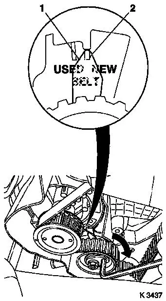
Adjust toothed belt tension
| • |
Release toothed belt tension roller
|
| • |
Turn adjustment eccentric in the direction of the arrow
(clockwise) until pointer (1) is aligned with the notch mark at the
toothed belt tension roller (2).
| – |
Adjust used toothed belts to the marking USED
|
| – |
Adjust new toothed belts to the marking NEW
|
|
| • |
Tighten toothed belt tension roller bolt 20 Nm
|
|
|
|
| 39. |
Check toothed belt tension
| • |
Turn crankshaft (720°)
Note: Pointers on the
toothed belt tension roller and notch mark must align.
| – |
Adjust used toothed belts to the marking USED
|
| – |
Adjust new toothed belts to the marking NEW
|
|
|
| 40. |
Install lower part of toothed belt cover
| • |
Clip to rear toothed belt cover
|
|
| 42. |
Attach camshaft sensor
| • |
Insert bolts with locking compound (red)
|
| • |
Connect wiring harness plug.
|
|
| 43. |
Install upper part of toothed belt cover
| • |
Clip to rear toothed belt cover
|
|
| 45. |
Install ribbed V-belt tensioner
| • |
Tension ribbed V-belt tensioner.
|
|
| 46. |
Attach crankshaft ribbed V-belt pulley
| • |
Tighten bolt 95 Nm + 30° +
15°
|
| • |
Insert front sealing plug
|
|
| 47. |
Install ribbed V-belt
Note: Note running
direction and installation position
| • |
Release ribbed V-belt tensioner
|
|
| 48. |
Install ribbed V-belt cover
|
| 50. |
Mount right front wheel.
|
| 52. |
Fasten right front wheel.
|
| 53. |
Install air cleaner housing
| • |
Attach engine vent hose
|
| • |
Connect wiring harness plug.
|
|
| 54. |
Install engine cover.
| • |
Unscrew oil filler pipe cap
|
| • |
Screw on oil filler pipe cap
|
|
| 56. |
Calibrate steering angle sensor
| • |
Switch on ignition
Note: Rotate the
steering wheel one time from its right-hand to its left-hand
stop.
|
|
| 57. |
Program volatile memories
|
| 58. |
Check engine oil level, if necessary correct.
| • |
Observe specified engine oil quantity
|
|
|
