|
J340100 Engine, Remove and Install (Z 14 XE, Z 16
YNG without AC, LHD)
Note: KM-6394 must be used as of model year 04 instead of
KM-6169-1 .
|
Warning: When using
vehicles running on natural gas, observe the particular procedures
and method of use, warning instructions and safety regulations.
1. Open bonnet
Important: On
vehicles as of model year 04 with ESP - the steering angle sensor
loses its basic adjustment each time the battery is disconnected.
It must be recalibrated.
|
|
2. Disconnect battery
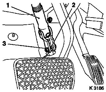
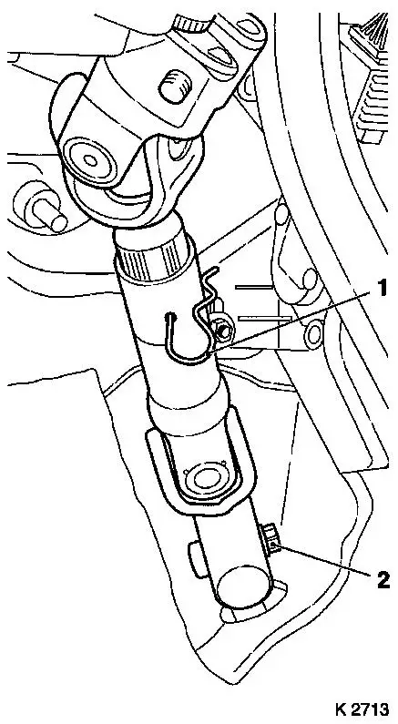
3. Install steering intermediate shaft
(1)
- Remove lower clamp pin (2)
- Steering in straight ahead position
- Engage steering lock
- Remove steering intermediate shaft
- Caution: Do not alter steering wheel position
4. Loosen front wheels
|
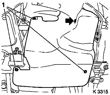
5. Release upper front panelling
|
|
6. Raise vehicle
7. Remove front wheels
|
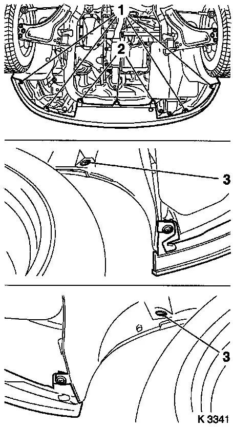
8. Release lower front panelling
- Disconnect wiring harness plug
- Remove 3 clips (2)
- Remove 4 bolts (1)
- Remove 2 nuts (3)
|
|
9. Detach front panelling
- Note: 2 people
- Remove and close the hose – high-pressure –
Headlamp washer system
|
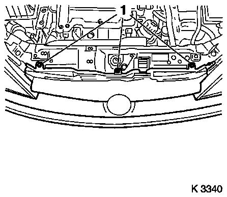
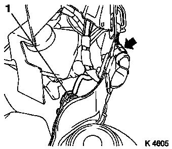
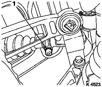
10. Remove ribbed V-belt cover
- Remove 3 bolts (1)
- Remove clip (arrow).
|
|
|
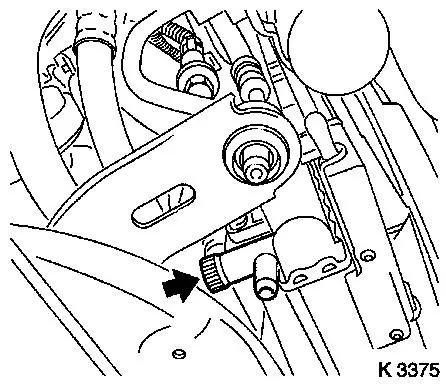
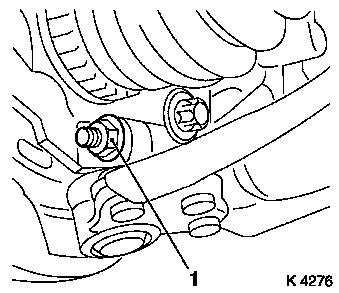
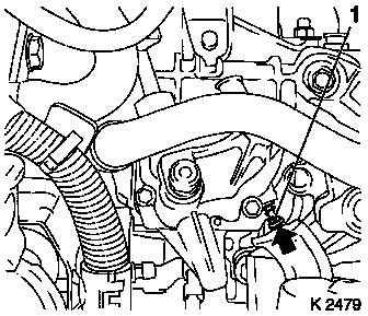
11. Drain coolant
- Place collecting basin underneath.
- Open drain bolt (arrow)
|
|
12. Lower vehicle
|
13. Remove engine cover
- Unscrew oil filler pipe cap
- Remove 2 bolts
- Screw on oil filler pipe cap
|
|
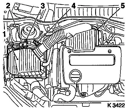
14. Remove air cleaner housing (1)
- Disconnect wiring harness plug
- Intake air temperature sensor (4), tank vent valve (2)
- Unclip tank vent valve
- Remove air intake pipe
- From throttle valve module
- Detach engine vent hose (5)
- Remove air intake hose
- Remove bolt (3)
|
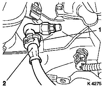
15. Detach throttle body module
preheater return hose (1)
- From throttle valve module
|
|
16. Detach heater fluid hoses (2)
|
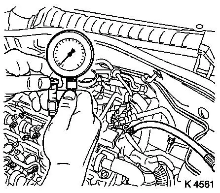
17. Reduce fuel pressure
- With KM-J-34730-91
- Caution: Observe safety measures and national legislation
- Unscrew test connection protective cap
- To fuel manifold pipe
|
|
18. Remove fuel line
|
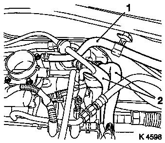
19. Unclip brake servo vacuum line
(1)
|
|
20. Remove catalytic converter control
oxygen sensor wiring harness plug (2)
|
21. Detach fuel evaporation hose
- From throttle valve module
|
|
22. Detach pressure line for central
release (2)
- Remove cover of brake fluid reservoir
- Top up brake fluid reservoir to "MAX" marking
- Attach MKM-558-10
- Disengage retaining clip (1) with a screwdriver
- Suspend pressure line for central release
- Note: Collect escaping brake fluid
- Clamp retaining clip
|
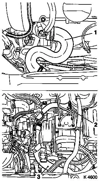
23. Remove upper radiator hose (1)
|
|
24. Remove lower radiator hose (3)
25. Detach hose for coolant compensation tank (2)
|
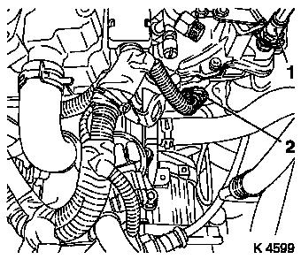
26. Remove wiring harness for engine
management
- Disconnect wiring harness plug
- Combination plug (1)
- Lower wiring harness plug for engine control unit (2)
- Reversing light switch (3)
- Unclip wiring harness and lay aside
|
|
|
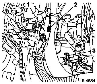
27. Detach engine wiring harness
- Remove rubber seal
- Lift water deflector
- Detach ground cable from battery.
- Detach battery positive cable
- Remove positive terminal
- Disconnect combination plug (1)
- Unclip wiring harness
- Remove cable harness and lay aside
|
|
28. Attach radiator
29. Raise vehicle
30. Close coolant drain bolt
|
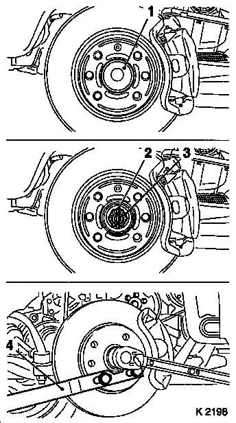
31. Detach axle shafts
- Remove protective caps (1)
- Remove split pin (2)
- Attach KM-468-B (4)
- At front wheel hub
- Use wheel bolts
- Unscrew nut (3)
- Hold with KM-468-B
- Remove discs
|
|
|
32. Detach tie rods
- From steering knuckle
- Remove 2 nuts
- Press off tie rods
|
|
|
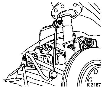
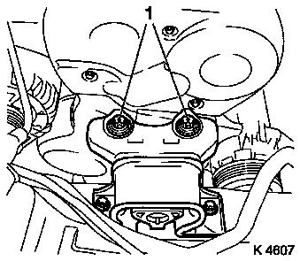
33. Remove pendulum
- From spring strut support tube
- Remove 2 nuts
- Note: Counterhold with open-ended wrench
|
|
|
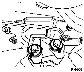
34. Detach guide joints
- From steering knuckle
- Remove 2 nuts (1)
|
|
35. Press out axle shafts
36. Raise vehicle
|
37. Remove exhaust system.
- Remove silencer
- Release clamp
- Detach 3 damping rings
- Remove front exhaust pipe
- Remove wiring harness for oxygen sensor, catalytic converter
control
|
|
38. Remove exhaust system
- Detach exhaust system
- Note: 2 people
39. Remove shift linkage.
|
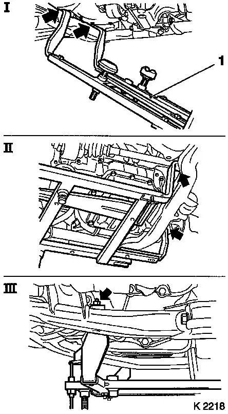
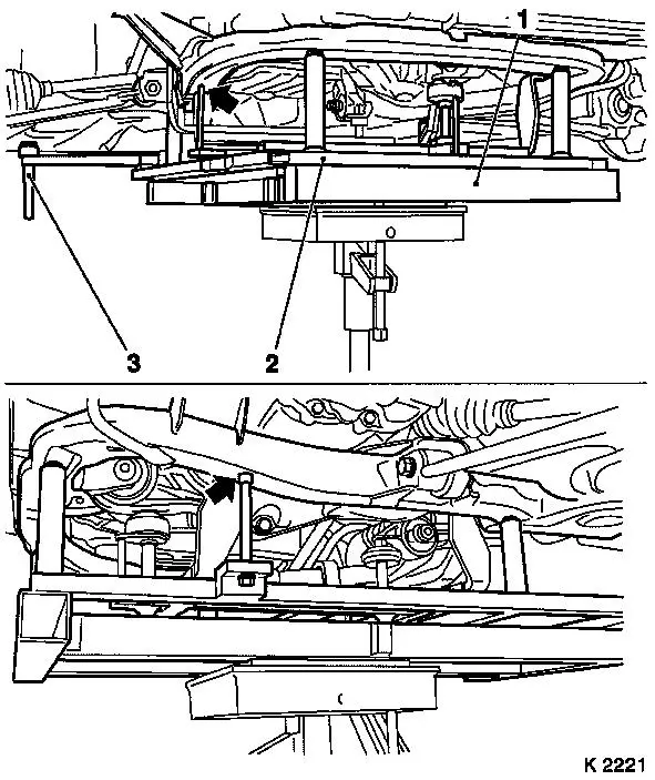
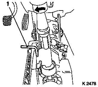
40. Attach KM-6169 (1)
- Place left of KM-6169 onto front axle body (arrows, illus.
I)
- Note: Guide pin must be seated in bore in front axle body
- Attach both right holders on the front axle body (arrows,
Illus. II).
- Note: Guide pin must be seated in bore in front axle body
(arrow, Illus. III)
- Tighten bolts
|
|
|
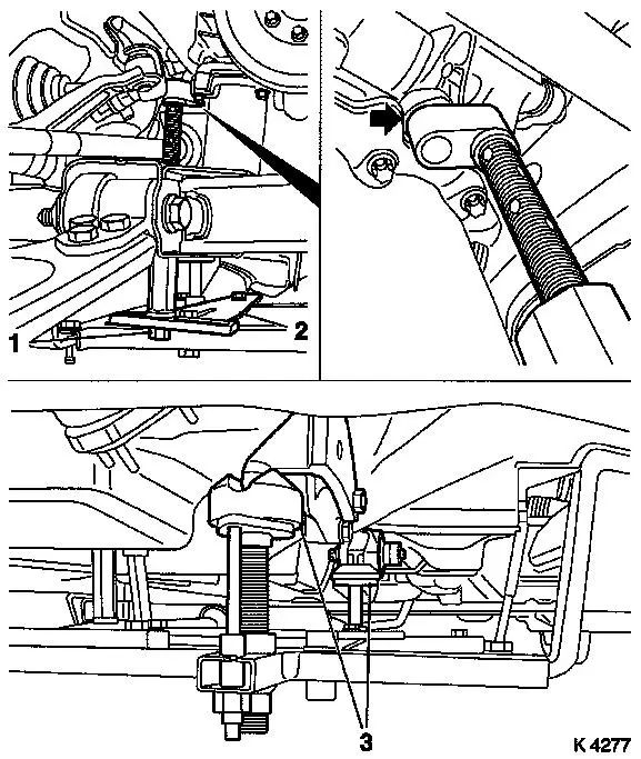
41. Install support
- To KM-6169
- Adjust bracket (2) for support
- Screw on nut (1)
|
|
42. Adjust supports
- Transmission side
- Note: Turn spindles until the mounts (3) are positioned at the
guide journals free of play
- Engine timing side
- Insert journal of the support in the bore of the cylinder block
without play (arrow)
- Tighten nuts (1)
43. Lower vehicle
|
44. Remove adapter for right engine
bracket
|
|
|
45. Remove left engine bracket
adapter
|
|
46. Raise vehicle
|
47. Insert hydraulic jack
|
|
48. Attach KM-6168 (2)
- Apply KM-6168
- On KM-904
- Note: Lower bodywork positioning pins (3)
- Position KM-6168
- Without play under front axle body
- Note: Note centring points in front axle body
|
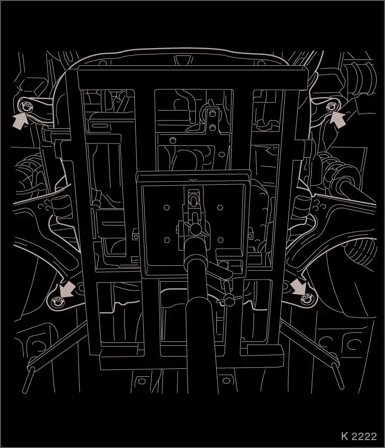
49. Detach front axle body
- Remove 4 bolts (arrows)
- Caution: The removal of the front axle body with an impulse or
impact screwdriver is not permitted
|
|
50. Lower drive unit
- Note: 2 people
- Caution: Carefully lower front axle body with engine and
transmission downwards out of engine compartment
- Do not damage attaching parts
51. Pull out drive unit
52. Check thread of clamping nut
- 4 off
- Caution: Before installing front axle body, the threads of the
clamping nuts must be checked for free movement, replace clamping
nut if necessary.
53. Push in drive unit
- Note: Secure bodywork positioning pins in upper position
54. Raise drive unit
- Note: 2 people
- Caution: Carefully move front axle body with engine and
transmission upwards into the engine compartment
- Do not damage attaching parts
- Insert body positioning pins in body positioning holes
55. Attach front axle body
- Renew bolts
- Tighten bolts (90 Nm / 70 lbf. ft. + 45° + 15°.)
56. Remove hydraulic jack
57. Lower vehicle
58. Fasten left engine bracket
adapter
- Renew bolts
- Tighten bolts (80 Nm / 59 lbf. ft. + 45° + 15°)
59. Attach adapter for right engine
bracket
- Renew bolts
- Tighten bolts (60 Nm / 44 lbf. ft. + 30° + 15°.)
60. Release radiator
61. Raise vehicle
62. Detach supports
- Engine timing side
- Transmission side
63. Detach KM-6169
64. Install shift linkage.
65. Attach exhaust system
66. Attach exhaust system
- Replace gasket
- Replace nuts
- Tighten nuts (25 Nm / 18 lbf. ft.)
- Install damping rings
- Attach rear muffler
- Connect oxygen sensor (catalytic converter control) cable
harness plug.
67. Lower vehicle
68. Install axle shafts
69. Attach guide joints
- Replace nuts
- Tighten bolts (60 Nm / 44.5 lbf. ft.)
70. Attach pendulum.
- Replace nuts
- Tighten nuts (65 Nm / 48 lbf. ft.)
- Note: Counterhold with open-ended wrench
71. Attach tie rods
- Replace nuts
- Tighten nuts (35 Nm / 26 lbf. ft.)
72. Attach axle shafts
- Replace nuts
- Attach KM-468-B
- Tighten nuts (120 Nm / 89 lbf. ft.)
- Loosen nuts
- Tighten nuts (20 Nm / 15 lbf. ft. + 90°)
- Replace split pins
- Note: If necessary, turn nut back until one split pin hole
aligns with the next castellated nut groove
- Install protective caps
73. Install ribbed V-belt cover
- Screw in bolts
- Install clip
74. Position front panelling
- Note: 2 people
- Install high-pressure headlamp washer hose
75. Fasten lower front panelling
- Install clips
- Tighten bolts
- Tighten nuts
- Connect wiring harness plug.
76. Attach front wheels
77. Lower vehicle
78. Fasten upper front panelling
79. Fasten front wheels
- Tighten bolts (110 Nm / 81 lbf. ft.)
80. Attach engine wiring harness
- Route wiring harness
- Connect wiring harness plug.
- Install positive terminal
- Attach positive cable
- Connect ground cable.
- Fasten cable harness
- Install rubber seal
81. Attach wiring harness for engine
management
- Route wiring harness
- Connect wiring harness plug.
- Attach wiring harness
82. Attach pressure line for central
release
- Note: Pressure line must engage audibly
- Detach MKM-558-10
- Bleed hydraulic clutch actuation – see operation
"Hydraulic Clutch Actuation, Bleed " in group "K".
- Screw on cover of brake fluid reservoir
83. Connect lower radiator hose
84. Connect hose for coolant compensation tank
85. Install upper radiator hose
86. Connect heater fluid hoses
87. Attach preheater return hose for throttle valve module
88. Connect wiring harness plug for
oxygen sensor, catalytic converter control
89. Attach fuel line
90. Attach brake servo vacuum line
- Note: Connection must engage audibly
91. Connect fuel evaporation hose
92. Install air cleaner housing
- Tighten bolt
- Install air intake hose.
- Attach engine vent hose
- Install air intake pipe
- Clip in tank vent valve
- Connect wiring harness plug.
93. Install engine cover
- Unscrew oil filler pipe cap
- Insert retaining lugs
- Tighten bolts (8 Nm / 6 lbf. ft.)
- Screw on oil filler pipe cap
- Note: Note cable routing
|
94. Install steering intermediate
shaft
- Note: Wheels in straight-ahead position
- Release steering lock
- Push on steering intermediate shaft
- Note: Bore hole for clamp bolt must be on the flat-milled side
of the steering journal
- Insert clamp pin
- Replace nut (2)
- Adjust length compensator
- Tighten nut (22 Nm / 16 lbf. ft.)
- Remove KM-6181
|
|
|
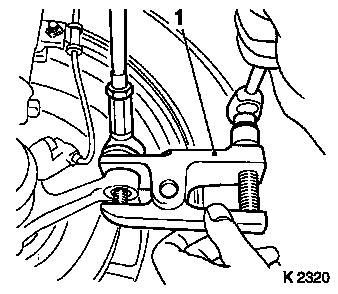
95. Arrest transmission shift linkage
|
|
- Unclip manual shift lever cover
- Arrest shift lever and shift lever housing
- Engage locking pin (1) in adjustment bore in shift cover by
turning shift rod to the left (direction of 3rd gear)
|
|
96. Raise vehicle
97. Fasten clamp
- Tighten bolt (12 Nm / 9 lbf. ft. + 90° + 90° to +
90° + 90° + 45°)
98. Lower vehicle
99. Check transmission shift
linkage
- Detach KM-527-A
- Note: Locking pin in adjustment bore is released automatically
when first shifting towards "R"
- Engage all gears
- Clip in manual shift lever cover
100. Top up coolant
- Note: Top up and bleed cooling system – see operation
"Cooling System, Top Up and Bleed".
- Observe specified coolant quantity
101. Connect battery
102. Calibrate steering angle
sensor
Note: Rotate the
steering wheel one time from its right-hand to its left-hand
stop.
103. Program volatile memories
104. Close bonnet
|
