|
Replace valve stem seal (Z 12 XE, Z 12 XEP, Z 14
XEP, with air conditioning, LHD)
 Remove Remove
| 2. |
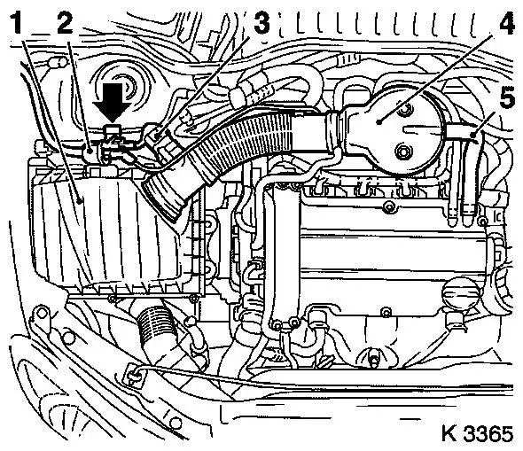
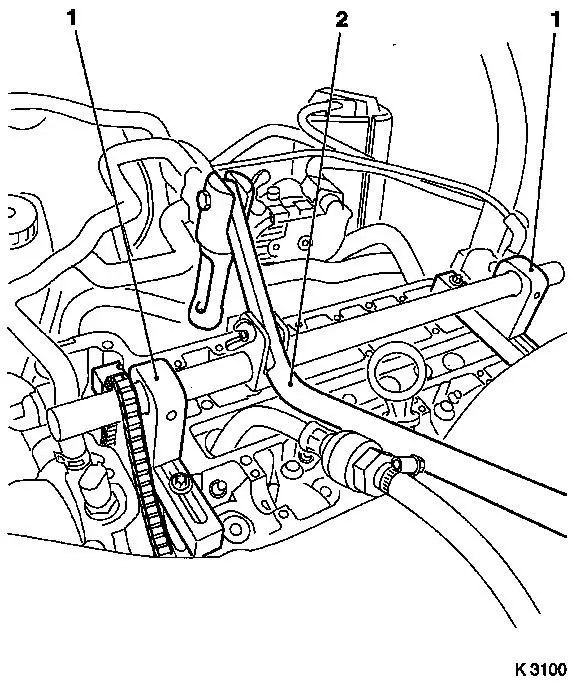
Remove air cleaner housing (1)
| • |
Disconnect 2 wiring harness plugs
| – |
Hot film mass air flow sensor (3), tank vent valve (2)
|
|
| • |
Remove suction pipe (4)
| – |
Detach engine vent hose (5)
|
|
| • |
For Z 12 XEP, Z 14 XEP: detach air intake hose
|
|
|
|
| 3. |
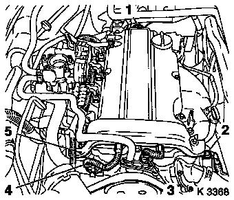
Remove wiring harness for engine management
| • |
Disconnect 4 wiring harness plugs
| – |
Oil pressure switch (2), coolant temperature sensor (3),
camshaft sensor (4) and ignition module (1)
|
|
| • |
Unclip wiring trough (5)
|
| • |
Set wiring harness to one side
|
|
|
|
| 4. |
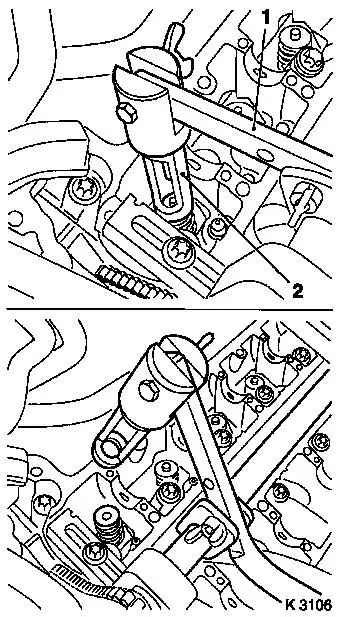
Remove ignition module
| • |
Remove ignition module cover
|
| • |
Extract using KM-6009 (1)
Note: Do not tilt
|
|
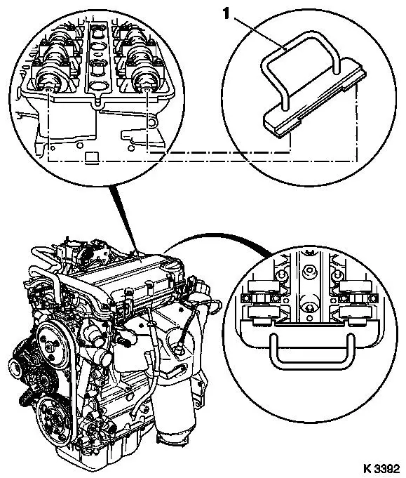
| 5. |
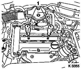
Remove cylinder head cover
| • |
Detach 2 engine vent hoses
|
|
|
|
| 7. |
Remove ribbed V-belt cover
|
|
|
| 8. |
Make guide mark on crankshaft belt pulley (arrow)
| • |
180° offset to no.1 cylinder TDC mark
|
|
|
|
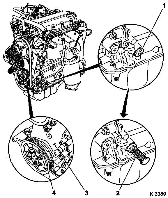
|
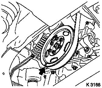
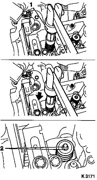
| 9. |
Remove closure bolt for crankshaft bearing bridge (1)
|
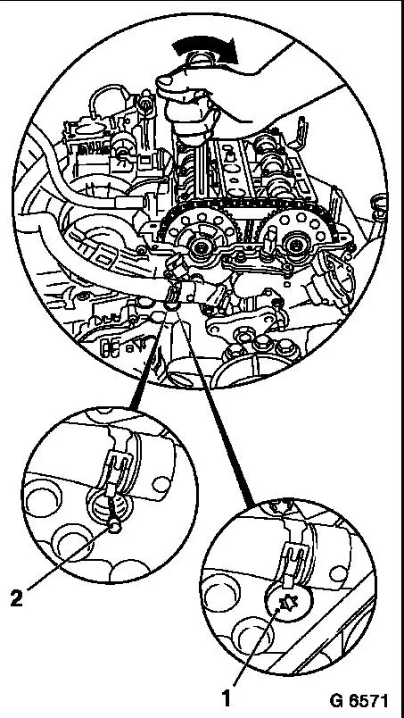
| 11. |
Set no.1 cylinder to TDC
| • |
Turn crankshaft uniformly until KM-952 engages
| – |
Mark on crankshaft belt pulley (4) must line up with lug (3) on
timing case
|
|
|
|
|
| 12. |
Insert KM-953 (1)
| • |
KM-953 must engage in camshaft
groove
|
|
|
|
| 13. |
Lock crankshaft
| • |
Apply parking brake
| – |
Wheels must be in contact with ground
|
|
|
|
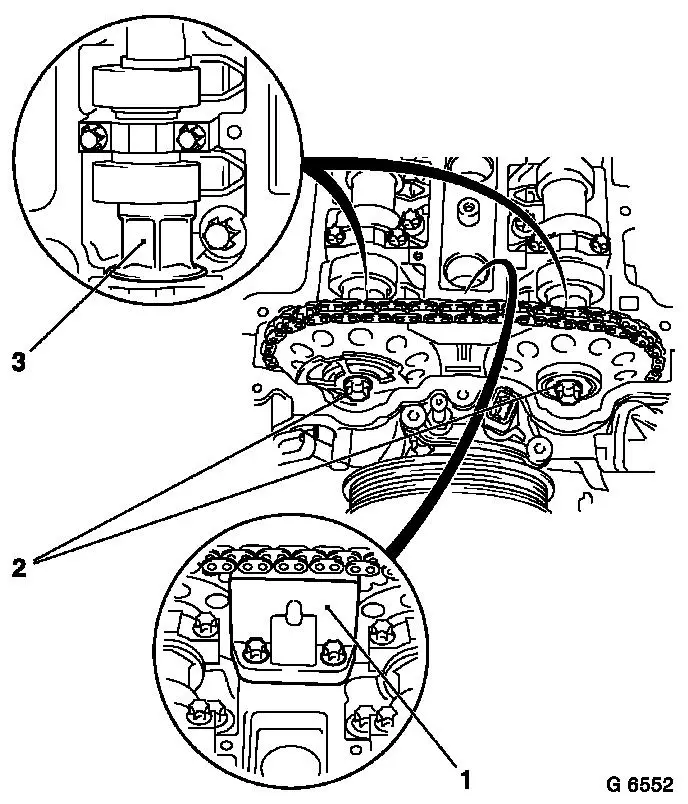
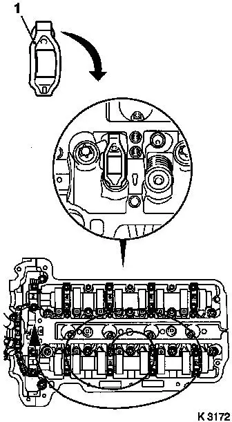
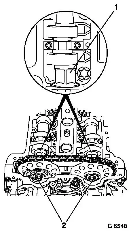
| 14. |
Lock chain tensioner
| • |
Unscrew closure bolt (1)
|
| • |
Load intake camshaft in direction of arrow via hexagonal
section using an open-ended spanner
|
|
|
|
|
| 15. |
Remove sliding rail (1)
|
| 16. |
Detach camshaft sprockets
| • |
Unscrew 2 bolts (2)
| – |
Counterhold camshafts at hexagonal section (3)
|
|
| • |
Remove phase sensor disc
|
|
|
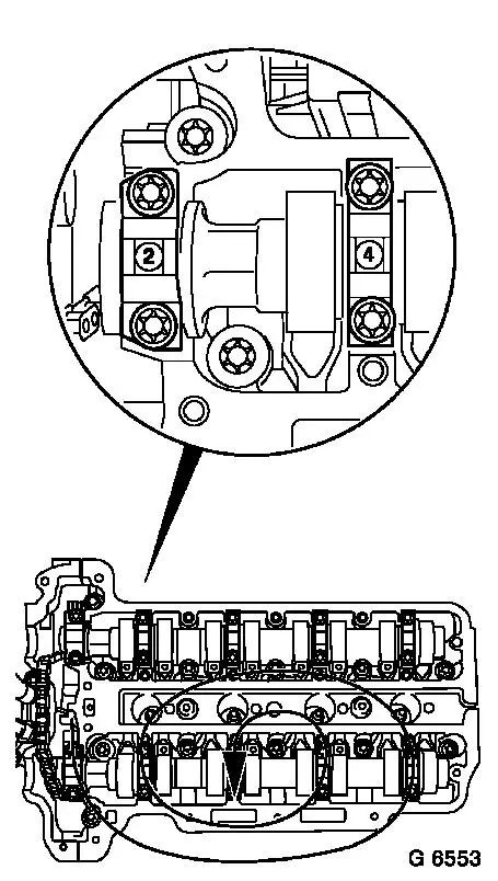
| 17. |
Remove exhaust camshaft
| • |
Remove camshaft bearing cap
|
| • |
Release camshaft bearing cap working in inward spiral from
outside in steps of 1/2 to 1 turn
| – |
Camshaft must be evenly released from the bearing seats
|
|
|
| 18. |
Remove intake camshaft
| • |
Remove camshaft bearing cap
|
| • |
Release camshaft bearing cap working in inward spiral from
outside in steps of 1/2 to 1 turn
| – |
Camshaft must be evenly released from the bearing seats
|
|
|
|
|
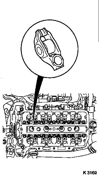
| 19. |
Remove 16x roller cam follower
Note: Observe
allocation.
|
| 20. |
Unscrew 4x spark plugs with KM-194-E
|
|
|
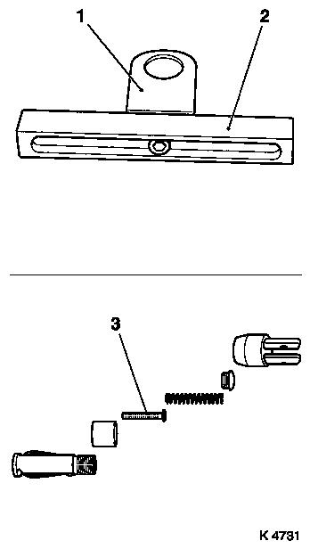
| 21. |
Complete automatic valve spring compressor
| • |
Adjust supports
| – |
Position support heads (1) in centre of support bases (2) and
tighten
|
|
| • |
Complete lever arm
| – |
Using joint, removal head
|
|
| • |
Insert assembly head MKM-6086-200
Note: Comply with
manufacturer's instructions
| – |
Insert thrust piece -5a (3)
|
|
|
|
|
|
| 22. |
Attach automatic valve spring compressor
| • |
Attach supports (1)
| – |
Insert installation shaft in supports
|
| – |
Line up assembly shaft in central position above spark plug
hole
|
|
| • |
Install Lever Arm (2)
Note: Removal head must
point to intake side
|
| • |
Secure installation shaft
|
|
| 23. |
Install compressed air adapter
| • |
Screw into spark plug thread of 1st cylinder
|
| • |
Apply compressed air to 1st cylinder
|
|
|
| 24. |
Remove 2x cylinder no.1 intake valve springs
| • |
Carefully push valve spring down with lever arm (1)
| – |
Removal head (2) must be vertically above the valve stem
|
|
Important: Observe
allocation.
|
| • |
Remove valve head, valve spring
Note: Do not use
magnetised tools
|
|
|
|
| 25. |
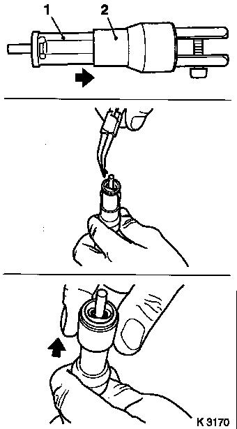
Replace 2x valve stem seals
| • |
Attach new valve stem seal to valve stem
|
| • |
Drive in to stop using KM-958
|
|
|
|
| 26. |
Install intake valve springs for cylinder no.1
| • |
Insert valve spring, valve head
|
| • |
Insert valve keepers in assembly head MKM-6068-200 (1)
| – |
Push plastic clamping sleeve (2) towards lever arm mounting
|
| – |
Insert valve keepers with taper facing the valve
|
| – |
Push plastic clamping sleeve towards valve
|
|
|
|
|
| 27. |
Install valve keepers
| • |
Attach assembly head (1) to lever arm
|
Important: Assembly head must be
vertically above the valve stem. Valve keepers (2) must audibly
engage.
|
| • |
Carefully push valve spring down with lever arm (arrow)
|
|
Important: Do not make 2nd
attempt without checking that both valve keepers are in the
assembly head
|
| 28. |
Check installation position
| • |
Check seat of valve keepers
|
| • |
Ensure that pressure is being applied
|
|
|
|
| 29. |
Transfer lever arm
| • |
Install lever arm
Note: Dismantling head
must point to the exhaust side
|
|
| 30. |
Remove exhaust valve springs for cylinder no.1
| • |
Carefully push valve spring down with lever arm
Note: Removal head must
be vertically above the valve stem
|
Important: Observe
allocation.
|
| • |
Remove valve keepers, valve head, valve spring
Note: Do not use
magnetised tools
|
|
| 31. |
Replace 2x valve stem seals
| • |
Attach new valve stem seal to valve stem
|
| • |
Drive in to stop using KM-958
|
|
| 32. |
Install exhaust valve springs for cylinder no.1
| • |
Insert valve spring, valve head
|
| • |
Insert valve keepers in assembly head MKM-6068-200 (1)
| – |
Push plastic clamping sleeve (2) towards lever arm mounting
|
| – |
Insert valve keepers with taper facing the valve
|
| – |
Push plastic clamping sleeve towards valve
|
|
|
| 33. |
Install valve keepers
| • |
Attach assembly head to lever arm
|
Important: Assembly head must be
vertically above the valve stem. Valve keepers must audibly
engage.
|
| • |
Carefully push valve spring down with lever arm
|
|
Important: Do not make 2nd
attempt without checking that both valve keepers are in the
assembly head
|
| 34. |
Check installation position
| • |
Check seat of valve keepers
|
| • |
Ensure that pressure is being applied
|
|
| 35. |
Transfer compressed air adapter
| • |
Interrupt compressed air feed
|
| • |
Unscrew from spark plug thread of 1st cylinder
|
| • |
Screw into spark plug thread of 4th cylinder
|
| • |
Apply compressed air to 4th cylinder
|
|
| 37. |
Replace no.4 cylinder valve stem seals
|
| 38. |
Interrupt compressed air feed
|
| 40. |
Set cylinder no.3 to TDC
Note: Second person
required
| • |
Pull timing chain upwards
|
| • |
Turn crankshaft evenly (120°)
Note: Guide mark on
crankshaft belt pulley must line up with lug on timing case
|
|
| 41. |
Lock crankshaft
Note: Wheels must be in
contact with ground
|
| 42. |
Transfer compressed air adapter
| • |
Unscrew from spark plug thread of 4th cylinder
|
| • |
Screw into spark plug thread of 2nd cylinder
|
| • |
Apply compressed air to 2nd cylinder
|
|
| 43. |
Replace no.2 cylinder valve stem seals
|
| 44. |
Transfer compressed air adapter
| • |
Interrupt compressed air feed
|
| • |
Unscrew from spark plug thread of 2nd cylinder
|
| • |
Screw into spark plug thread of 3rd cylinder
|
| • |
Apply compressed air to 3rd cylinder
|
|
| 45. |
Replace no.3 cylinder valve stem seals
|
| 46. |
Interrupt compressed air feed
|
| 47. |
Remove automatic valve spring compressor
|
| 48. |
Remove compressed air adapter
|
| 51. |
Lock crankshaft
| • |
Pull timing chain upwards
|
| • |
Turn crankshaft uniformly until KM-952 engages
|
|
| 53. |
Install spark plugs
| • |
Tighten 4x with KM-194-D 25 Nm
|
|
| 54. |
Inspect components
| • |
Camshafts, camshaft covers, cylinder head, roller cam
followers
|
|
 Install
| 55. |
Insert roller cam follower
Note: Observe
allocation.
| • |
Coat sliding surfaces with MoS2 lubricating paste
|
|
| 56. |
Install intake camshaft
| • |
Coat sliding surfaces with MoS2 lubricating paste
|
| • |
Insert camshaft, camshaft bearing cap
Note: Observe
installation position and allocations
|
| • |
Install camshaft bearing cap
| – |
Tighten camshaft bearing caps in stages in spiral pattern from
inside to outside 8 Nm
|
|
|
| 57. |
Install exhaust camshaft
| • |
Coat sliding surfaces with MoS2 lubricating paste
|
| • |
Insert camshaft, camshaft bearing cap
Note: Observe
installation position and allocations
|
| • |
Install camshaft bearing cap
| – |
Tighten camshaft bearing caps in stages in spiral pattern from
inside to outside 8 Nm
|
|
|
|
|
|
| 58. |
Adjust camshafts
| • |
Insert KM-953 (1)
| – |
"Turn" the camshafts at hexagonal section (arrows)
|
|
|
|
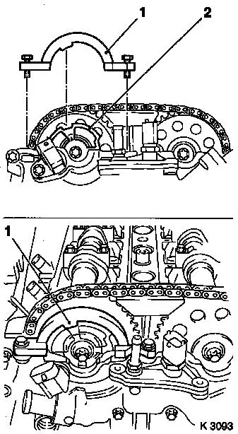
| 59. |
Attach camshaft sprockets
| • |
Attach intake camshaft sprocket with phase sensor disc (2)
Note: It must be
possible to rotate phase sensor disk by hand
|
| • |
Attach exhaust camshaft sprocket
|
|
| 61. |
Remove KM-955-1
| • |
Tighten chain tensioner closure bolt 50
Nm
|
|
| 62. |
Attach KM-954
Note: Rotate phase
sensor disk (2) until KM-954 (1) can be
attached to timing case
|
|
|
| 63. |
Fasten camshaft sprockets
Note: Tightening torque
of 10 Nm is used to secure the camshaft sprockets and the phase
sensor disk
| • |
Tighten 2 bolts (2) 10 Nm
Note: First tighten
intake camshaft sprocket bolt
| – |
Counterhold camshafts at hexagonal section (1)
|
|
|
| 64. |
Remove retaining tools
Note: Retaining tools
must not be used for counterholding
| • |
KM-952 , KM-953 , KM-954
|
|
| 65. |
Fasten camshaft sprockets
Note: Second person
required
| • |
Tighten 2 bolts 50 Nm + 60°
Note: First tighten
intake camshaft sprocket bolt
| – |
Counterhold camshafts at hexagonal section
|
|
|
| 67. |
Remove retaining tools
| • |
KM-952 , KM-953 , KM-954
|
|
| 69. |
Attach closure bolt of crankshaft bearing bridge
|
| 70. |
Install ribbed V-belt cover
|
|
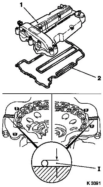
|
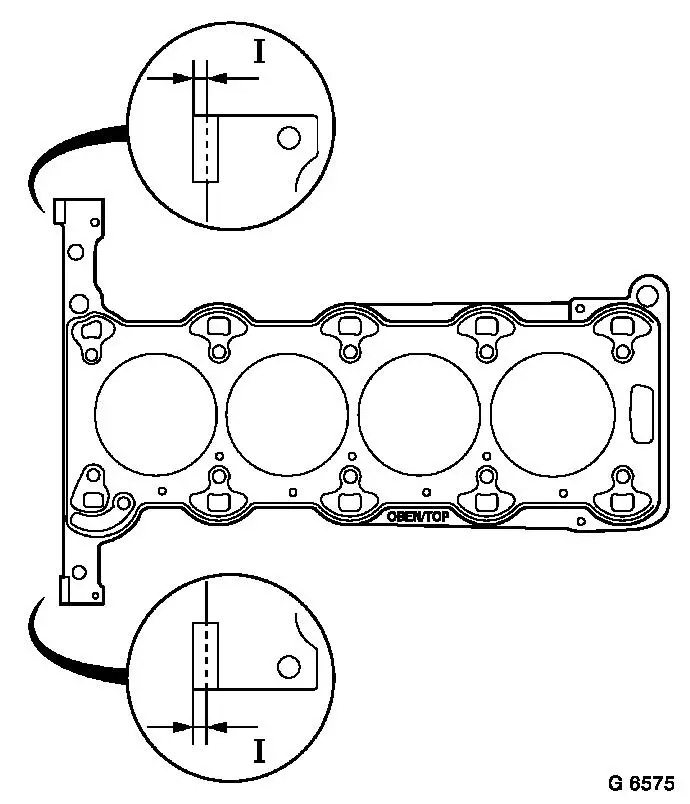
| 72. |
Attach cylinder head cover (1)
| • |
Renew gasket (2) and seal rings
|
| • |
Apply sealant (dimension l = 2 mm)
Note: Complete assembly
operations within 10 minutes
|
| • |
Attach engine vent hose
|
|
| 73. |
Install ignition module
| • |
Attach ignition module cover
|
|
| 74. |
Install engine management wiring harness
| • |
Connect 4 engine management wiring harness plugs
|
|
|
|
| 75. |
Install air cleaner housing
| • |
Attach suction pipe
| – |
Attach engine vent hose
|
|
| • |
For Z 12 XEP, Z 14 XEP: attach air intake hose
|
| • |
Connect 2 wiring harness plugs
|
|
|
