|
Relay Frame – Engine Compartment Light
Module, Remove and Install
 Remove Remove
| 2. |
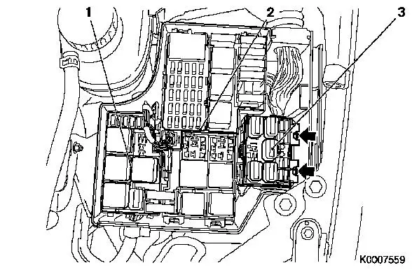
Detach cover of relay box
|
|
| 3. |
Remove relay frame, engine compartment fan module (1) 
|
| 4. |
Remove relay frame, engine compartment main fuse carrier (2)
|
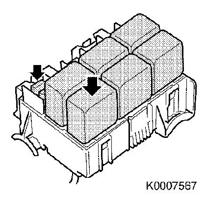
| 5. |
Unclip relay frame for engine compartment light module (3),
(arrows)
|
| 6. |
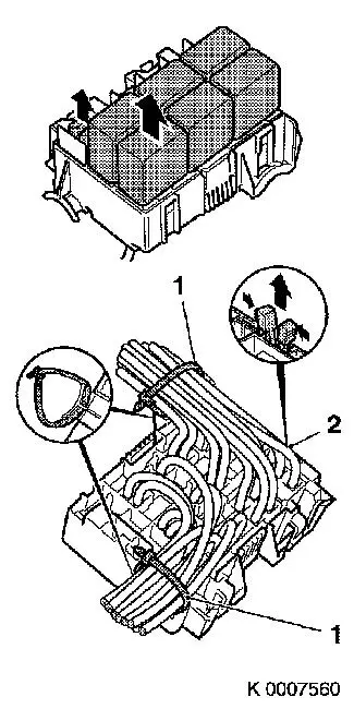
Release necessary wiring harnesses, disconnect necessary wiring
harness plugs and unscrew necessary earth connections
|
|
Important: Note the installation
positions of the relays and fuses.
|
| 7. |
Remove relays and fuses.
|
| 8. |
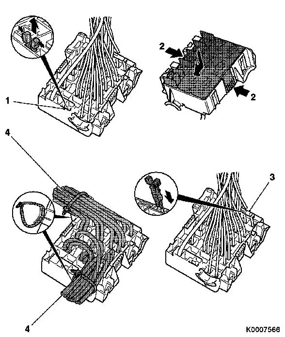
Remove cable ties (tape loops) (1)
|
| 9. |
Compress head of housing retainer (2) and remove
|
|
|
| 10. |
Release secondary retainer
|
| 11. |
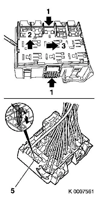
Release housing on both sides (1)
|
| 12. |
Lever up housing (2) and slide in direction (3)
Note: For a clearer
illustration, the cables are not shown.
|
| 13. |
Compress head of housing release (5) and secure the upper part
by inserting the housing retainer into the preliminary position
|
|
|
| 14. |
The individual cables must be replaced in the new housing one
by one if possible. If this is not possible, the cables must be
marked correspondingly
|
| 15. |
The secondary retainer must be released on the new housing.
|
| 16. |
The released housing must be secured with the housing
retainer
|
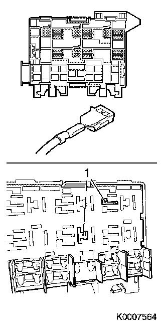
| 17. |
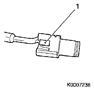
Before inserting into the new housing, the spring contacts must
be checked. If necessary, the locking mechanism (1) must be
corrected carefully
|
|
|
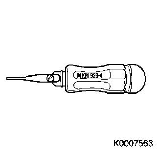
| 18. |
Unlocking tool required:
|
|
|
| 19. |
Release locking mechanisms of the RT 6.3-contacts with Special
Tool MKM-923-4 and pull out the
contacts
|
| 20. |
The locking mechanisms (1) for these contacts are in the
housing
|
|
|
|
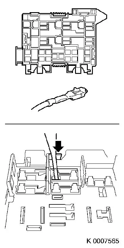
| 21. |
Release locking mechanism of the MP 2.8-contacts with Special
Tool MKM-923-4 and pull out the
contacts
|
| 22. |
The locking mechanisms are on the contacts
|
|
| 23. |
Insert the contacts that have not yet been inserted into the
previously noted chambers of the new housing
|
|
| 24. |
Compress head of housing retainer (1) and remove
|
| 25. |
Release secondary retainers (2) and push the upper part into
the limit position, upper and lower part are now flush
|
| 26. |
Secure upper part by inserting the housing retainers (3)
|
| 27. |
Check correct seating of all the contacts
|
| 28. |
Secure cables at 2 points (4) with tape loops
|
|
 Install
|
| 29. |
Insert relays, fuses and cover flap (arrows)
|
|
| 30. |
Fasten released wiring harnesses
| • |
connect disconnected wiring harness plugs
|
| • |
connect released earth connections
|
|
| 31. |
Install relay carrier, engine compartment fan module
|
| 32. |
Install relay frame, engine compartment main fuse carrier
|
| 33. |
Insert relay frame for engine compartment light module
|
| 36. |
Program volatile memories
|
| 37. |
Electrical function check
|
|
