Bosch Alternator, Overhaul
Remove and disassemble alternator, see corresponding
operation.
Cleaning petrol can be used as a cleaning agent.
Electrical windings should only brought into contact with the
cleaning agent briefly. Cleaned parts should be immediately blown dry with
compressed air.
Wash out ball bearing. Replace defective ball bearings.
Clean housing parts.
Clean stator and claw pole rotor.
|
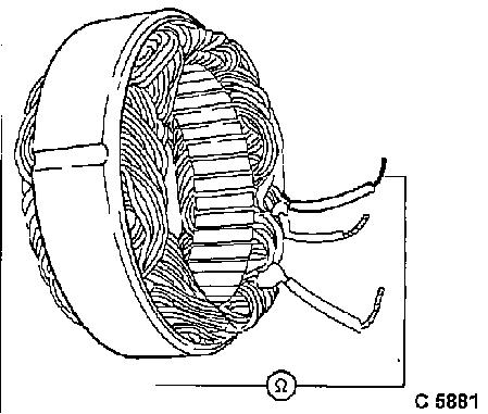
Check all phases of stator winding for short circuit to
ground using ohmmeter.
Ohmmeter should indicate infinity.
Replace stator with short circuit to ground.
|

|
|
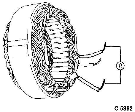
Check all phases of stator winding for short-circuited
windings using ohmmeter (ohmic resistance).
Resistance between two phases is measured.
Hold probes alternately on ends of windings.
See Technical Data for test values
Replace stator with short-circuited winding.
|
|
|
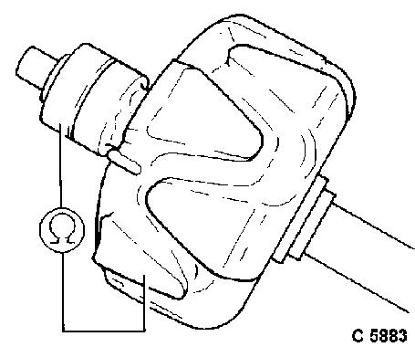
Check rotor winding and slip rings for short circuit to
ground using ohmmeter.
Ohmmeter should indicate infinity.
Replace rotor with short circuit to ground.
|
|
|
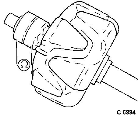
Check rotor winding for short-circuited winding using
ohmmeter (ohmic resistance).
Resistance of excitation winding from slip ring to slip ring is
measured.
See Technical Data for test values
Replace rotor with short circuit.
|
|
|
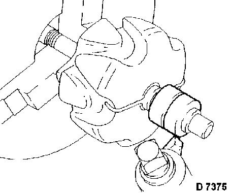
Clean and polish slip rings with fine emery paper (grain
500-600) - on lathe.
Turn down uneven slip rings; dimensions, see Technical Data.
When doing this, only remove as much material as is
necessary to even out the worn sections. Afterwards, slip rings should again
be polished and blown dry.
|
|
|
Diodes, Check
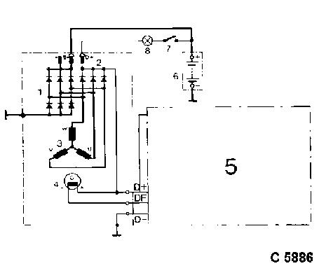
Circuit diagram of an electronically-regulated alternator
1 Rectifier diodes
2 Excitation diodes
3 Stator winding
4 Excitation winding
5 Electronic voltage regulator
(connected)
6 Battery
7 Ignition lock
8 Charge telltale
|
|
With the diode test described in the following, individual
diodes can be tested for continuity, interruption, short circuit and blocking
action. The test result allows only qualitative statments to be made about the
effectiveness of the diode or the condition of the barrier layer. If an exact
check of the diodes is required, use diode-checking equipment - observe
manufacturer's instructions.
If any diode is faulty, replace diode plate completely.
When checking diodes using test lamps, only use equipment up
to 24 volts DC.
|
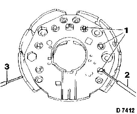
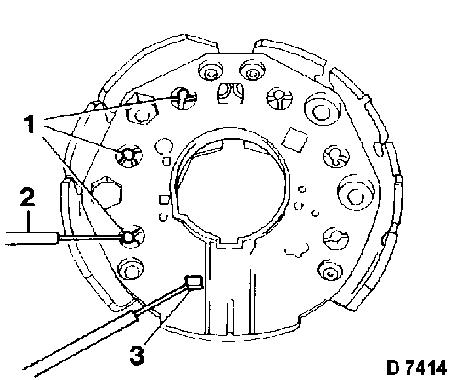
Negative Diodes (1), Check Individually
Hold positive probe (2) to diode housing and other probe (3)
to diode connection.
Test lamp must light up.
Excharge probes and check again.
Test lamp must not light up.
Negative diodes show continuity from housing to connection
and block in the reverse direction.
If any diode is faulty, replace diode plate completely.
|
|
|
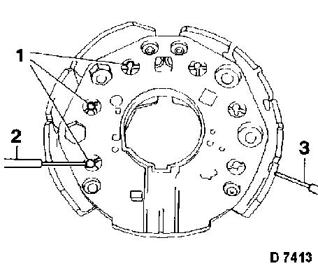
Positive Diodes (1), Check Individually
Hold positive probe (2) to diode connection and other probe
(3) to diode housing.
Test lamp must light up.
Exchange probes and check again.
Test lamp must not light up.
Positive diodes show continuity from connection to housing
and block in the reverse direction.
If any diode is faulty, replace diode plate completely.
|
|
|
Excitation Diodes (1), Check Individually
Excitation diodes are checked in the same way as positive
diodes.
The positive probe (2) must be held to the diode connection
and the other probe to the contact rail (3).
If any diode is faulty, replace diode plate completely.
|
|
|
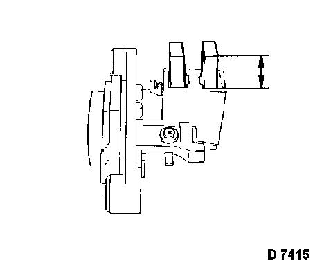
Carbon Brushes, Check
Replace carbon brushes if worn down to minimum dimension -
see Technical Data.
When soldering in new carbon brushes, maintain projection -
see Technical Data.
Important:
Solder must not run up strand.
Check new brushes for ease of run in the brush holders.
|
|
