|
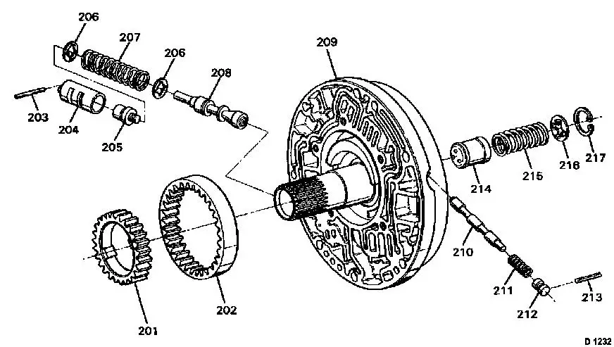
Fluid Pump, Disassemble and Assemble
|
|
201
|
Pump gear, driving
|
|
202
|
Pump gear, driven
|
|
203
|
Roll pin, bushing
|
|
204
|
Guide sleeve, pressure switch valve
|
|
205
|
Boost valve
|
|
206
|
Spring seat, pressure regulator valve
|
|
207
|
Spring, pressure regulator valve
|
|
208
|
Pressure regulator valve
|
|
209
|
Fluid pump housing
|
|
210
|
Control valve converter clutch
|
|
|
|
211
|
Spring, control valve
|
|
212
|
Closure Plugs
|
|
213
|
Roll pin
|
|
214
|
Accumulator piston, throttle signal
|
|
215
|
Spring, accumulator
|
|
216
|
Spring seat, accumulator
|
|
217
|
Retaining ring
|
|
Note: The fluid pump
may only be disassembled for checking and cleaning purposes. Repair
is not anticipated.
|
 Remove Remove
Remove fluid pump from transmission – see operation
"Assemblies, Remove and Install".
 Disassemble
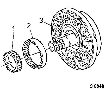
Mark installation position of the driving (1) and the driven (2)
pump gear and remove from the fluid pump housing (3).
Remove converter clutch control valve, accumulator for throttle
signal, boost valve and pressure regulator valve.
The illustration of the individual parts can be seen in Figure D
1232.
|
|
 Inspect
Check all components of fluid pump for wear or damage, replacing
complete fluid pump, if necessary.
 Assemble
Coat spring seat (206) with installation grease and pre-install
on pressure regulator valve. Note installation position of spring
seats (206 and 216) – the flat side faces away from the
spring – see illustration D 1232.
Coat boost valve (205) with installation grease and pre-install
in liner (204) – see illustration D 1232.
The pump gears must be installed with the marks facing
upwards.
 Install
Install fluid pump in transmission – see operation
"Assemblies, Remove and Install".
|
