|
Automatic Transmission, Remove and Install (in
Vehicles with 4 Cylinder Petrol Engine)
|
 Remove Remove
Put selector lever in "N". Disconnect ground cable of battery.
If present, remove engine compartment cover (10 screws).
In vehicles with OHC engine: Remove DIS ignition module –
see operation "DIS Ignition Module, Remove and Install" in group
"J".
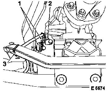
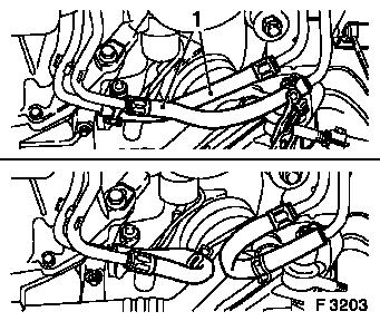
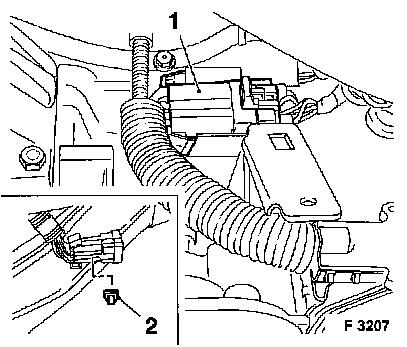
Disconnect oxygen sensor wiring harness plug (1) (For Y 22 XE /
Z 22 XE engines: x 2) and unclip from bracket (2) – cut cable
ties (3).
|
|
|
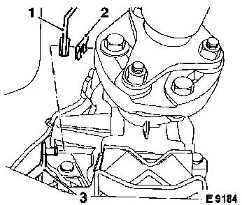
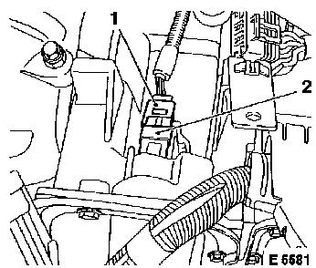
Disconnect selector rod (3) from selector intermediate lever
(1). For this, remove retaining plate (2).
|
|
|
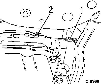
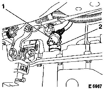
Disconnect plug connection (1) from transmission output speed
sensor. Cut off cable tie (2).
|
|
|
Unscrew exhaust support from front exhaust pipe.
|
|
|
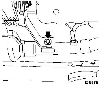
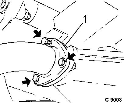
Unscrew front exhaust pipe from catalytic converter. Remove
gasket (1).
|
|
|
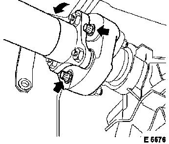
Propshaft from output flange (3 screws with nuts).
Press propshaft backwards and suspend on right side of
transmission tunnel.
|
|
|
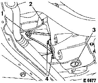
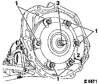
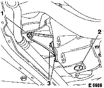
Only loosen engine supports on both sides of engine (1) and
unscrew from converter housing (4).
Unscrew lower bolt for transmission to engine (2) on both
sides..
Remove cover cap (3) from converter housing.
|
|
|
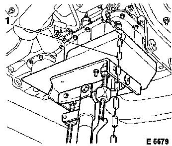
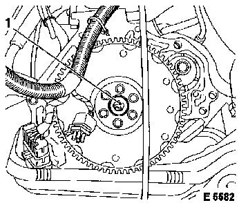
Remove cover plate (1) for converter housing.
Converter from drive plate (6 screws). Counterhold through bore
hole in converter housing using lever.
|
|
|
Disconnect fluid cooler lines to connection hoses (1) with hose
clamp pliers (e.g. Hazet 798, jaw width 40 mm).
Caution
Fluid escapes – stop egress of fluid by inserting
connection hoses into adjacent pipes (F 3203, lower half).
|
|
|
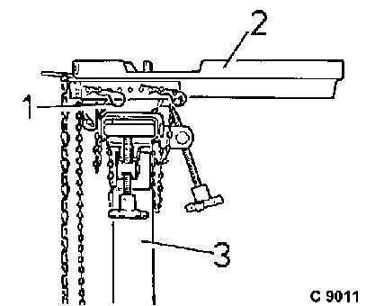
Use hydraulic jack (3) with commercially available transmission
lifter adapter No. 09 00 094 (1) and mounting plate F 09 18 021 (2)
for fixing the transmission.
|
|
|
Fix transmission to adapter and secure.
Caution
Check for correct seating of adapter. Avoid damage of
transmission attaching parts.
|
|
Remove
|
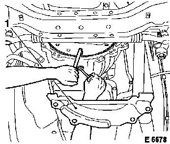
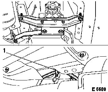
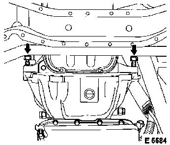
Unscrew transmission crossmember from vehicle underbody (2
bolts, arrows). Lower transmission a small amount.
Vent hose from upper side of transmission.
Bend bracket (1) open for wiring harness from left transmission
side, make wiring harness accessible.
|
|
|
Carefully unclip wiring harness plug X 8 (1) for selector lever
position switch from bracket with screwdriver and disconnect.
Caution
When wiring harness plug X 8 is pressed off, the fastening clip
(2) becomes damaged and must be replaced.
|
|
Remove
|
Disconnect wiring harness plug X 10 (4 pin, 1) from connection
plug (2) on intermediate housing.
|
|
|
Disconnect wiring harness plug X 9 (7 pin, 1) from connecting
plug (2) on main housing.
|
|
|
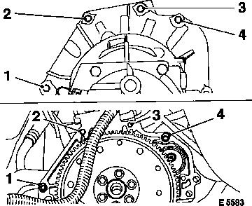
Unscrew upper fastening screws from transmission to engine (1 to
4)..
Disconnect transmission from engine and lower.
|
|
Caution
|
For installation of new transmission – see operation
"Transmission, Replace".
Before installation of a new transmission, blow out fluid
cooling hoses with low pressure compressed air to remove deposits
and remaining fluid from fluid cooler and fluid lines.
Clean threaded bore holes for microencapsulated bolts prior to
installation by cutting and insert the bolts themselves with
locking compound.
Coat centring seat (1) for the converter in the crankshaft with
lubricating grease.
|
|
|
If converter is correctly installed, the distance (2) between
front surface of the threaded fittings on the converter and the
front edge of the converter housing is 15 mm. Secure transmission
with chain on adapter.
Check easy movement of the threaded bore holes (1) in the torque
converter. Check centring pin (3) of the torque converter for
frictional rust, clean if necessary.
|
|
 Install
|
Raise transmission with hydraulic jack, align with engine and
install – ensure that centring pins on engine block engage in
converter housing.
Torque
Upper screws (1 to 4) for converter housing to engine – 60
Nm / 44 lbf. ft. Long screw on starter.
|
|
|
2 lower bolts for converter housing to engine – 60 Nm / 44
lbf. ft.
Install
Connect wiring harness plug X 9 (7 pin) to connecting plug on
main housing.
Connect wiring harness plug X 10 (4 pin) to connecting plug on
intermediate housing.
|
|
Install
Connect wiring harness plug X 8 of selector lever position
switch and install on transmission with new clip.
Vent hose to neck on upper side of transmission. Connect wiring
harness plug to transmission output speed sensor – fasten
wiring harness to cable retainer on transmission housing (bend lugs
together). Fasten wiring harness with cable tie.
Remove retaining chain and lift transmission with hydraulic
jack.
Torque
Transmission crossmember to vehicle underbody – 45 Nm / 33
lbf. ft., re-cut threads and insert fastening bolts with locking
compound. Remove hydraulic jack and adapter.
Converter to drive plate (6 screws) – 30 Nm / 22 lbf. ft.
Counterhold through bore hole in converter housing using lever.
Install
Attach connection hoses for fluid cooler lines to relevant pipes
(hose clamp pliers, e.g. Hazet 798, jaw width 40 mm).
|
Install cover plate for converter housing.
Torque
Engine supports to converter housing (3) – 22 Nm / 16 lbf.
ft.
Tighten support on both sides of engine (1) – 45 Nm / 33
lbf. ft.
Attach cover cap (2) to converter housing.
|
|
Torque/angle method
|
Propshaft to output flange, use 3 new screws with nuts:
Tighten Torx screws M10 in 2 stages – 50 Nm / 37 lbf. ft.
+ 75° to 90°.
Hex screws M12 – 95 Nm / 70 lbf. ft.
|
|
Torque
Catalytic converter to front muffler – 25 Nm / 18.5 lbf.
ft. Use new gasket with flanging pointing towards exhaust
outlet.
Support to front exhaust pipe – 20 Nm / 15 lbf. ft.
Install
Connect selector rod to selector intermediate lever and secure
with retaining plate. Connect wiring harness plug to oxygen sensor
and clip into bracket. Fasten wiring harness with cable tie.
Only in vehicles with OHC engine: Install DIS ignition module
– see operation "DIS Ignition Module, Remove and Install" in
group "J".
With all vehicles: Check transmission fluid level – see
operation "Transmission Fluid Level, Check and Correct".
 Adjust Adjust
Adjust selector lever linkage – see operation "Selector
Lever Linkage, Adjust". If available, connect engine cover (10
bolts). Connect battery.
|
