|
Automatic Transmission, Remove and Install
(Vehicles with V6 Engine)
 Remove Remove
|
Selector lever in position "N". Disconnect battery.
Raise vehicle. If present, remove engine cover (10 bolts).
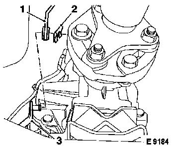
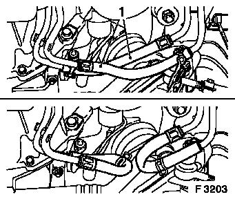
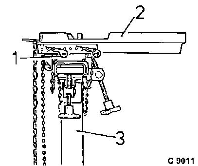
Remove retaining plate (2), detach selector rod (3) from
intermediate selector rod (1).
|
|
|
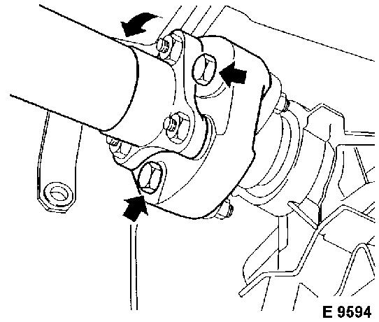
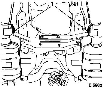
Unscrew propshaft from drive flange (3 screws and nuts).
Collapse propshaft and suspend from vehicle underbody.
|
|
|
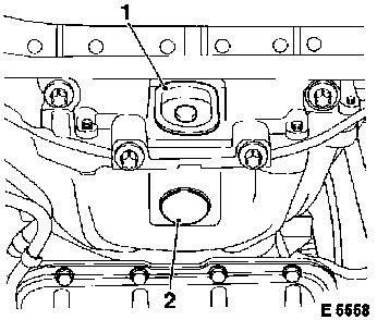
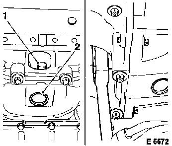
Remove cover caps from fluid pan (1) and converter housing
(2).
|
|
|
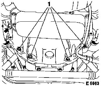
Remove 6 screws from torque converter. Turn torque converter on
crankshaft pulley.
|
|
|
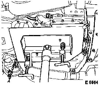
Disconnect fluid cooler lines to connection hoses (1) with hose
clamp pliers (e.g. Hazet 798, jaw width 40 mm).
Caution
Fluid escapes – stop fluid egress by short-circuiting
connection hoses to adjacent pipe (lower section of
illustration).
|
|
Remove
|
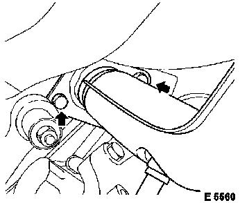
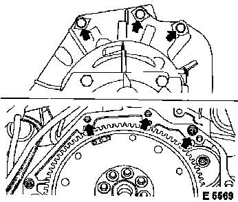
Unscrew front exhaust pipes on exhaust manifold (2 bolts each,
arrows).
|
|
|
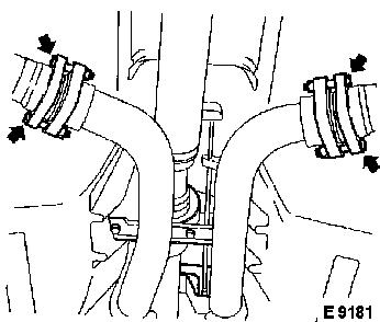
Disconnect front exhaust pipes from catalytic converters (4
bolts and nuts).
|
|
|
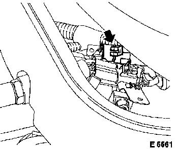
Disconnect wiring harness plugs (for Y 26 SE, 2 x each left and
right) for oxygen sensor left (arrow) and right. Place harnesses
out of way (downwards). Cut cable ties.
|
|
Remove
|
Unscrew front exhaust pipes from supports (1) and remove.
|
|
|
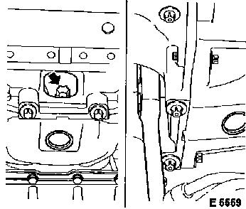
Unscrew 3 lower screws (arrows) from converter housing to
engine. Unscrew 4 lower screws (1) from converter housing to fluid
pan.
|
|
|
Mount transmission with transmission jack attachment No. 09 00
094 and clamp plate F 09 18 021 on hydraulic jack.
|
|
|
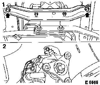
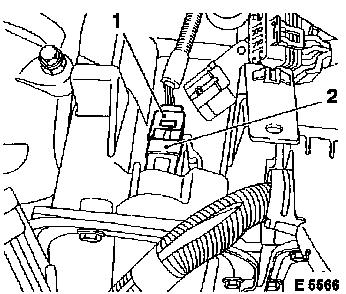
Unscrew transmission crossmember (1) and lower transmission
carefully.
Secure transmission on transmission lifter adapter.
Remove vent hose from neck on upper side of transmission housing
(2).
|
|
|
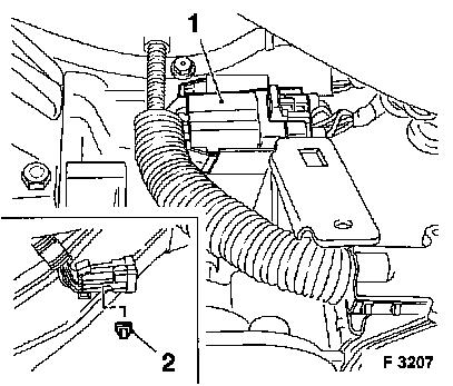
Carefully unclip wiring harness plug X 8 (1) for selector lever
position switch from bracket with suitable screwdriver and
disconnect.
Caution
When wiring harness plug X 8 is pressed off, the fastening clip
(2) becomes damaged and must be replaced.
|
|
|
Remove
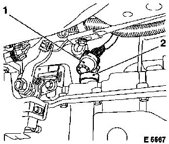
Disconnect wiring harness plug X 10 (4 pin, 1) from connection
plug (2) on intermediate housing.
|
|
|
Disconnect wiring harness plug X 9 (7 pin, 1) from connecting
plug (2) on main housing.
|
|
|
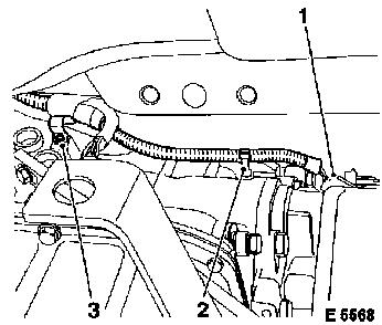
Detach wiring harness plug (1) from transmission output speed
sensor. Separate cable tie (2). Bend open cable bracket (3) and
expose wiring harness.
|
|
|
Unscrew 3 upper transmission bolts.
Press transmission off engine – if necessary, disconnect
torque converter from drive plate carefully using tyre lever.
Lower transmission.
Caution
Before installation of a new transmission, blow out fluid
cooling hoses with low pressure compressed air to remove deposits
and remaining fluid from fluid cooler and fluid lines.
Clean threaded bore holes for microencapsulated bolts prior to
installation by cutting and insert the bolts themselves with
locking compound.
|
|
 Install
|
Use hydraulic jack (3) with transmission jack attachment No. 09
00 094 (1) and clamp plate F 09 18 021 (2) for mounting the
transmission.
Install transmission to adapter and secure with chain.
|
|
 Inspect
|
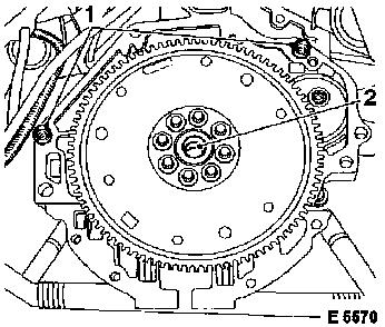
Seat of guide sleeves (1) in engine flange.
Check centring seat for the torque converter in the crankshaft
(2) and then coat with lubricating grease.
|
|
|
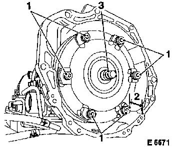
Check seating for torque converter on fluid pump shaft –
Dimension "2" = 15 mm.
Check free movement of threaded bores (1) in torque
converter.
Check centring journal (3) of torque converter for frictional
rust and lubricate.
Install
Raise hydraulic jack. Align transmission with engine and
attach.
|
|
|
Torque
|
3 lower fastening bolts (arrows) for converter housing to
engine
|
- 60 Nm / 44 lbf. ft.
|
|
4 lower fastening bolts (1) for converter housing to fluid pan
(M8)
|
- 20 Nm / 15 lbf. ft.
|
|
4 lower fastening bolts (1) for converter housing to fluid pan
(M10)
|
- 40 Nm / 29.5 lbf. ft.
|
|
|
Torque
|
Insert 6 screws (1) for torque converter in sequence and tighten
(turn on crankshaft pulley) – 30 Nm / 22 lbf. ft.
Align bore holes by turning torque converter through opening (2)
using a lever.
Install
Insert cover caps into fluid pan and converter housing.
|
|
|
Torque
Lower hydraulic jack slightly – 3 upper screws for
converter housing to engine – 60 Nm / 44 lbf. ft.
Install
Connect wiring harness plug X 10 (4 pin) to connecting plug on
intermediate housing.
|
|
Connect wiring harness plug X 9 (7 pin) to connecting plug on
main housing.
Connect wiring harness plug X 8 of selector lever position
switch and install on transmission with new clip.
Connect wiring harness plug to output speed sensor –
fasten wiring harness to cable bracket on transmission housing
(bend tab down). Fasten wiring harness with cable tie.
Attach vent hose to neck on upper side of transmission housing.
Remove safety chain and raise transmission.
Torque
Transmission crossmember to vehicle underbody – 45 Nm / 33
lbf. ft., insert 2 bolts with locking compound.
Install
Attach front exhaust pipes to exhaust manifold (with new
gaskets), position supports for front exhaust pipes and screw on
– do not tighten yet.
Connect wiring harness plugs for oxygen sensors (Y 26 SE, 2 x
each left and right) and attach with cable ties.
Torque
Catalytic converters to front mufflers – 25 Nm / 18 lbf.
ft., if necessary, clean sealing surfaces.
Front exhaust pipes to exhaust manifold – 30 Nm / 22 lbf.
ft.
Supports to front exhaust pipes – 20 Nm / 15 lbf. ft.
Install
Attach connection hoses for fluid cooler lines to relevant pipes
(hose clamp pliers, e.g. Hazet 798, jaw width 40 mm). Attach
selector rod to intermediate selector lever and secure with locking
plate.
Torque/angle method
Propshaft to output flange, use 3 new screws with nuts:
Tighten Torx screws M10 in 2 stages – 50 Nm / 37 lbf. ft.
+ 75° to 90°.
Hex screws M12 – 95 Nm / 70 lbf. ft.
Inspect
Check transmission fluid level – see operation
"Transmission Fluid Level, Check and Correct". Selector Lever
Linkage, Adjust – see operation "Selector Lever Linkage,
Adjust". If available, install engine cover (10 bolts). Connect
ground cable to battery.
|
