volkswagen Workshop Repair Guides

Volkswagen Workshop Service and Repair Manuals

Dismantling and assembling gearbox > < Removing and installing bonded rubber bushes for gearbox carrier
4 Speed Manual Gearbox 020
Controls, Housing
Removing and installing gearbox

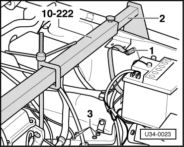
Service installation of the 5 speed manual gearbox .

Removing

 
U34-0023
  •      1 -     → Disconnect battery earth cable
  •      2 -     Install and tension lifting appliance
  •      3 -     Detach left gearbox mounting
 
U34-0024
  •      4 -     → Remove TDC sender unit with a spark plug spanner (part No. 311 012 205 A) and turn engine with V belt until the lug on the flywheel (33° before TDC) appears in the TDC sender unit hole.

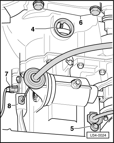
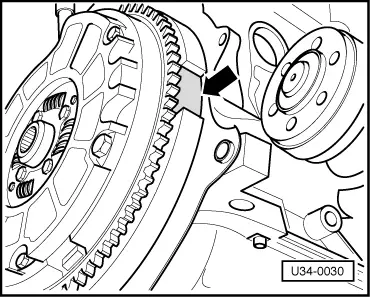
Note:

The engine and gearbox can only be separated whit flywheel in this position.

On vehicles with 81 KW engine the drive flange on engine side has a flat on it. To separate engine and gearbox, position flat towards flywheel.

  •      5 -     Disconnect speedo cable and seal hole with a rubber cap to prevent oil from running out when engine is taken out.
  •      6 -     Remove upper bolts attaching gearbox to engine
  •      7 -     Pull reversing light wire off
  •      8 -     Disconnect clutch cable

Modification

 
U34-0025

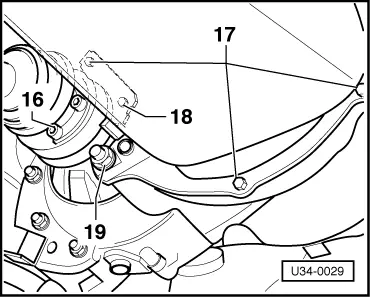
From 9/74 (Except 81 KW engine)

→ Depression 76° before TDC instead of lug 33° before TDC (3 recesses on flywheel instead of 2, => page 34-34 ).

Mod.:

From 11.78 securing point 18 changed from stud and nut to bolt (M 12 x 58). At the same time the recess ( => page 34-34 ) and the lug 76° before TDC in flywheel, were discontinued. When removing gearbox, turn it until there is sufficient clearance between flywheel and drive flange. Its is no longer necessary to align flywheel or flange.

 
U34-0026
  •      9 -     → Disconnect linkage from selector shaft.
  •      10 -     Take relay lever off bearing rod.
 
U34-0027
  •      11 -     → Detach earth wire from gearbox.
  •      12 -     Remove starter.
  •      13 -     Detach torque strut from gearbox and body.
 
U34-0028
  •      14 -     → Detach rear gearbox mounting
  •      15 -     Detach left drive shaft and hang up on a wire hook.
 
U34-0029
  •      16 -     → Detach right drive shaft and hang up on a wire hook.
  •      17 -     Remove screws securing large cover plate. Plate stays on engine.
  •      18 -     Remove screw securing small cover plate and take plate off.
  •      19 -     Remove nut or bolt.
  • ‒ Press gearbox off dowel sleeves and take it out downwards. (Two mechanics required).

Installing

 
U34-0030

→ Install by reversing the removal sequence

=> Repair Group 10; Engine

Caution
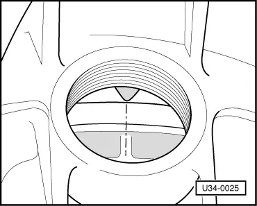
The recess in the flywheel must be positioned level with the drive flange -arrow-.

Tightening torques:

Gearbox to engine (M 12)

- 75 Nm

Gearbox to engine (M 10)

- 45 Nm

Drive shaft to flange

- 45 Nm

Left mounting to gearbox

- 40 Nm

Shift rod to linkage

- 15 Nm

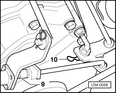
When gearbox has been installed, check length of selector rod (b) and adjust if necessary => page 34-8

Renewing gearbox

From assembly date 07 085 to 24 085, gearboxes with high-mounted starter and side pressure shift system where installed. When renewing, use Port No. 020 300 043 B - for downward pressure system ( without reverse catch).

This box must be converted to side pressure system as follows:

  • ‒ Remove selector shaft and install 020 301 235 (or shaft from old box).
  • ‒ Install retaining screw 020 301 241 A and adjust as detailed on => page 34-17 , under B.

This conversion is essential as otherwise there is no reverse catch.

Dismantling and assembling gearbox > < Removing and installing bonded rubber bushes for gearbox carrier