volkswagen Workshop Repair Guides

Volkswagen Workshop Service and Repair Manuals

Service installation of the 5 speed manual gearbox > < Dismantling and assembling gearbox
4 Speed Manual Gearbox 020
Controls, Housing
Removing and installing Housing
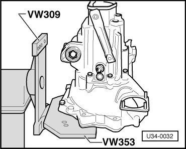
Removing

 
U34-0032
  • ‒ → Installing gearbox in repair stand - VW.
 
U34-0033
  • ‒ → Installing gearbox in repair stand - Audi.
  • ‒ Pull clutch rod out downwards.
 
U34-0034
  • ‒ → Fitting support bar for drive shaft - VW
  • A - Locknut M 12.
  • ‒ Lift VW 295a into contact with drive shaft with screw and lock.
 
U34-0035
  • ‒ → Fitting support bar for drive shaft - Audi.
  • A - Locknut M 12.
 
V34-0102
  • ‒ → Remove cap, circlip and washer from drive flange.
  • ‒ Pull flange off.
  • Screw two M 8 x 30 bolts through slots into flange.
  • ‒ Take cover off.
  • ‒ Lever circlip off release shaft.
  • ‒ Take off release shaft , clutch lever, return spring, release bearing and sleeve.
 
34-214
  • ‒ → Lever plugs -arrows- out and take off 3 nuts.
  • ‒ Remove selector shaft retaining screw.
  • ‒ Remove bolt securing reverse gear shaft.
  • ‒ Screw reversing light switch out.
 
V34-2506
  • ‒ → Remove selector shaft end plug.
  • A - Spark plug spanner (Part No. 311 012 205 A).
  • ‒ Move selector forks to neutral and pull selector shaft out.

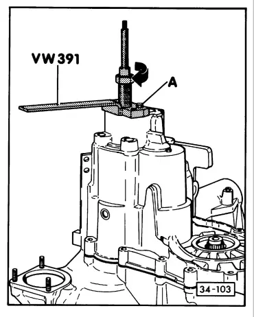
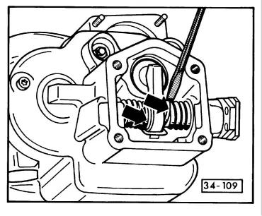
Note:

If the selector forks cannot be placed in neutral the selector shaft cannot be pulled out. Shaft can then be removed by force as follows:

 
U34-0036
  • ‒ → Take circlip -2- off (only on downward pressure system).
  • ‒ Knock shaft -1- out.
  • ‒ Sheet metal housing -3-, shift finger -4- and sleeve -5- remain in housing -6-.
  • ‒ If 1st, 2nd or reverse gear are engaged.
  • ‒ When knocking shaft out, place a nut between sheet metal housing -3- and gearbox -6- as a support -arrow-
  • ‒ Renew damaged parts (selector shaft, shaft, selector forks).
 
34-103
  • ‒ → Remove bolts attaching gearbox housing.
  • ‒ Pull housing off.
  • A - Screws two M 7 x 30 bolts (N 10 407.1) through the holes into the housing.
 
U35-0014

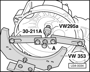
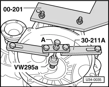
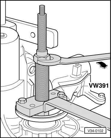
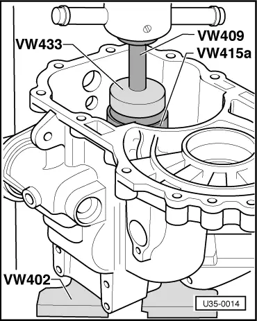
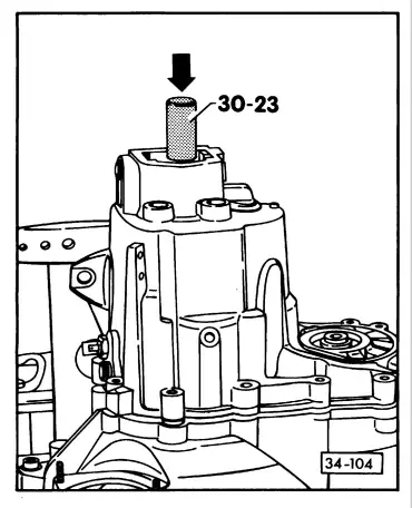
Installing

If drive shaft has not been dismantled, press drive shaft ball bearing off ; Fig.1 .

  • ‒ → Press drive shaft bearing into housing with shims in position.
 
35-061
  • ‒ → Insert clamping bolts and tighten nuts.
 
V35-0070
  • ‒ → Align reverse gear shaft. Spacing x must be the same.

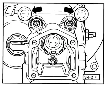
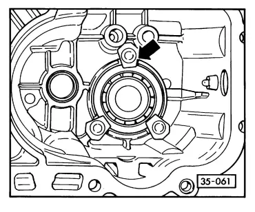
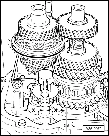
Before Knocking housing on:

 
34-104
  •      a -     Screw two M 8 studs into bearing housing to guide gearbox housing.
  •      b -     Ensure that the drive shaft is properly supported by bar 30-211 and adaptor VW 295 A.
  • ‒ → Knock housing on.
  • ‒ Screw in bolt securing reverse gear shaft.
  • ‒ Screw in bolts securing housing.
  • ‒ Move forks to neutral, insert selector shaft and install cover.
  • ‒ Install reversing light switch.
  • ‒ Install and adjust retaining screw for selector shaft => page 34-17
 
V34-2481
  • ‒ → Install drive flange.
  • ‒ Fit washer and circlip
 
U34-0038
  • ‒ → Press drive flange circlip into position.
  • ‒ Install cap.
  • ‒ Retighten nuts on clamping bolts to 1.5 mkg and fit plugs.
 
U34-0039
  • ‒ → Install drive shaft circlip
  • ‒ Install release bearing and sleeve. Fit release shaft, clutch lever and return spring. The bent ends of the spring contact the housing wall and the centre part hooks on to the clutch lever.
 
34-109
  • ‒ → Install locking ring (s) for release shaft.
  • ‒ Fit cover and insert clutch rod.

Modifications

Gearbox housing/end cover

From Assembly date 15 03 5:

The bore in the housing for the end cover was changed form tapered to cylindrical.

Repair instructions

(Gearbox up to 14 03 5)

When fitting a new gearbox housing use 020 301 051 A housing,end cover 020 301 232 A and boot 020 301 261 A.

 
U34-0040

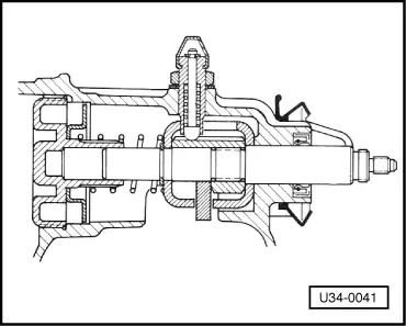
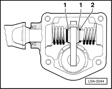
Selector shaft

Up to Assembly date 24 08 5:

Side pressure system.

→ Reverse catch provided by chamfer on selector shaft -arrow- and retaining screw.

 
U34-0041

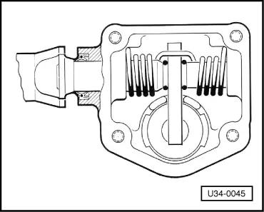
From Assembly date 25 08 5:

Downward pressure system.

→ Reverse catch moved to shift linkage. Chamfer on selector shaft discontinued, retaining screw modified, spring at end of shaft dropped.

 
U34-0042

Reversing light switch

From Assembly date 07 08 5.

→ The switch is mounted on a bracket -1- attached to the gearbox and operated by the selector shaft lever -2-.

Adjust or bend the bracket so that the reversing lights work properly.

 
U34-0043

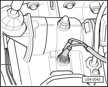
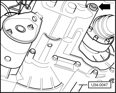
From Assembly date 05 04 6.

→ The switch is in the gearbox again.

Operated by a lug on the reverse gear selector fork (see => page 34-67 )

 
U34-0044

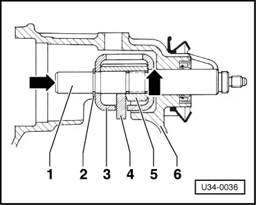
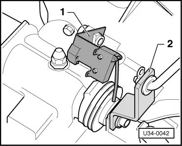
Clutch lever

From 15 03 5 to 16 03 7

→ Lever with shoulder -1-, secured with one circlip -2-.

 
U34-0045

From Assy. date 17 03 7:

→ Lever with no shoulder, secured with two circlips. Modified release shaft.

Note:

Up to 16 03 7

When installing the new shaft, the new lever and an additional circlip must be installed.

 
U34-0046

Checking oil level

Remove checking plug -arrow 1- with 5 mm Allen key. Oil must be up to lower edge of hole.

Putting oil in

→ Removing plug -arrow 2-.

Put in gear oil - SAE 80 or 80/90 to MIL-L 2105 (GL 4) specifications - until oil flows out of level checking hole.

Caution
Oil must be put in slowly to give it time to level out uniformly in the box. Stop for a brief period (30 seconds) if necessary.
 
U34-0047

Modification

From Assembly date 07 05 4

→ Level checking hole discontinued. Oil is put in and checked through the filler hole.

Service installation of the 5 speed manual gearbox > < Dismantling and assembling gearbox