volkswagen Workshop Repair Guides

Volkswagen Golf Mk1 Workshop Service and Repair Manuals

Piston and cylinder dimensions > < Subsequent machining of ignition timing notch
4 cyl. carburetor engine, mechanics (1.5, 1.6 and 1.8 litre engine)
Dismantling and assembling pistons and conrods
 
U13-0016
  • Piston rings
    • ◆ Offset gaps by 120°
    • ◆ Remove and install with piston ring pliers
    • ◆ "TOP" towards piston crown
    • ◆ Checking piston ring gap =>Fig. 1
    • ◆ Checking piston ring groove clearance => Fig. 2
  • Piston
    • ◆ Checking => Fig. 3
    • ◆ Mark installation position and cylinder number.
    • ◆ Arrow on piston crown faces pulley end
    • ◆ Install using piston ring clamp
    • ◆ Identification => Fig. 4
  • Conrod
    • ◆ Renew in sets only
    • ◆ Mark with respect to cylinder -A-
    • ◆ Installation position: Marks -B- face pulley end
    • ◆ Identification => Fig. 5
 
U13-0016
  • Conrod nut
    • ◆ Identification and tightening torque => Fig. 6
    • ◆ Lubricate thread and the support surface
    • ◆ To measure radial clearance tighten to 30 Nm, but do not turn further
  • Conrod cap
    • ◆ Installation position: Marks -B- face pulley end
  • Bearing shell
    • ◆ Watch position
    • ◆ Do not interchange used bearing shells
    • ◆ Ensure tight fit in the retaining lugs
    • ◆ Axial clearance Wear limit: 0.37 mm
    • ◆ Check radial clearance with Plastigage Wear limit: 0.12 mm
    • ◆ Do not rotate crankshaft when measuring the radial clearance
 
U13-0016
  • Cylinder block
    • ◆ Checking cylinder bore => Fig. 7
    • ◆ Piston and cylinder dimensions =>page 13-43
  • Conrod bolt
    • ◆ Identification => Fig. 8
  • Circlip
  • Piston pin
    • ◆ Heat piston to 60 °C if stiff
    • ◆ Removing and installing:
      dia. 22 mm with VW 207 c
      dia. 20 mm with VW 222 a
    • ◆ Identification => Fig. 9
    • ◆ Piston with short piston pin => Fig. 10
 
V13-0016

→ Fig.1     Checking piston ring gap

Push ring squarely from above into lower end of cylinder approx. 15 mm away from edge of the cylinder.

Piston ring

Gap

New

Wear limit

Compression ring

mm

0.30...0.45

1.0

2-piece oil scraper ring

mm

0.25...0.45

1.0

3-piece oil scraper ring

mm

0.25...0.50

1.0

 
V13-0687

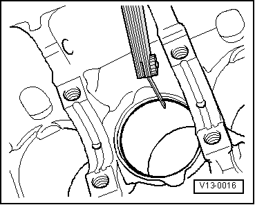
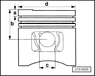
→ Fig.2     Checking piston ring groove clearance

Clean groove before checking.

Piston ring

Groove clearance

New

Wear limit

Compression ring

mm

0.02...0.05

0.15

Oil scraper ring

mm

0.02...0.05

0.15

 
V13-0010

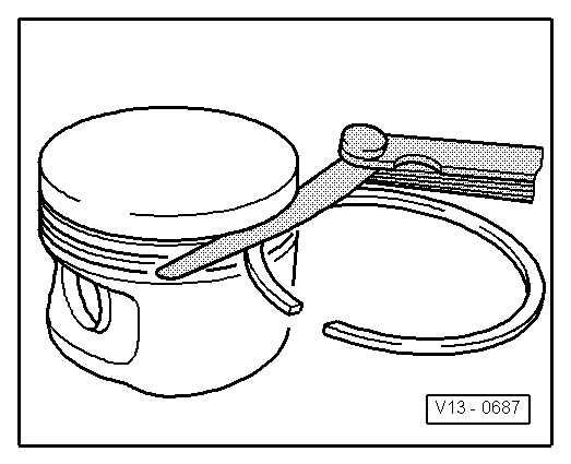
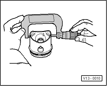
→ Fig.3     Checking pistons

Check approx. 10 mm from bottom of skirt offset by 90° with respect to piston pin axis.

Deviation from specified dimension: max. 0.04 mm.

 
U13-0017

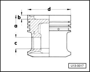
→ Fig.4     Piston distinguishing features

Engine codes

Dimension (mm)

a

b

dia. c

dia. d

EM, FN, FP, FR, FT

30.8

6.1

22

79.5

HM

30.8

- 1)

22

79.5

EW, RE

25.6

2.3

20

81.0

EX

22.2

4.4

20

81.0

FB, FD

30.4

- 1)

22

76.5

FH

30.4

6.0

22

76.5

FK

30.4

10.0

22

76.5

     1)     Flat piston

 
U13-0017

Engine codes

Dimension (mm)→

a

b

dia. c

dia. d

FV

30.4

7.5

22

79.5

GH

34.0

5.9

22

79.5

HN

25.6

2.3

20

81.0

JB

34.0

5.1

22

79.5

GY ä Engine
Nº 096787

27.9

1.0

22

75.0

 
U13-0023

Piston ring

Dimension (mm)→

a

b

dia. c

dia. d

GY Engine
Nº 096788 ä

8.9

39.8

20.0

74.985

Bore ø= 76.5 mm

 
V13-1130

Piston ring

Dimension (mm)→

a

b

dia. c

dia. d

AJD

28.4

0.7

76.5

22

BBV

26.45

1,5

76.5

20,4

Bore ø= 76.5 mm

Note:

When performing repairs, an engine may only be fitted with pistons and piston rings of the same desin and pistons from the same weight category.

 
U13-0018

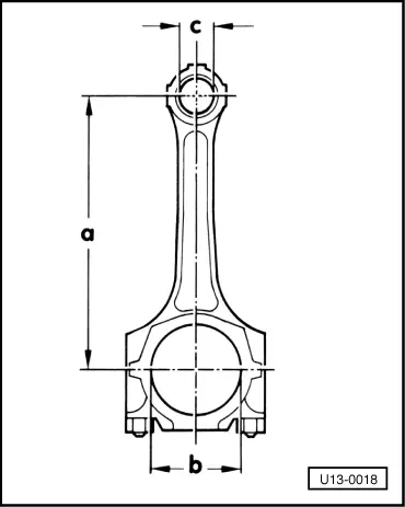
→ Fig.5     Connecting rod distiguishing features

Engine codes

Dimension (mm)

a

b

dia. c

EM, FB, FD, FH, FK, FN, FP, FR, FT, FV, GH, JB, GY, HM, AJD, BBV

136

49.0

22

EW, HN, RE, EX

144

50.6

20

 
U13-0019

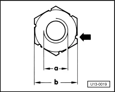
→ Fig.6     Conrod nut distinguishing features

Thread -a-

M9x1

M8x1

Width across flats -b-

14 mm

14 mm

(no notches)

(with notch)
-arrow-

Tightening torque

45 Nm

30 Nm + 1/4 turn (90°)

 
V13-0280

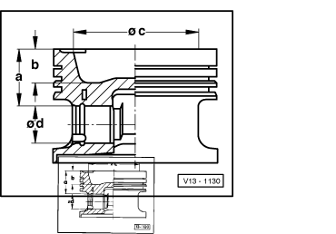
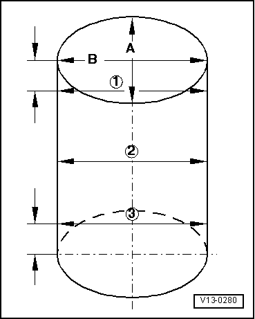
→ Fig.7     Checking cylinder bore

  • ◆ Measure bore at 3 locations crosswise in tranverse -A- and axial direction -B-.
  • ◆ Use 50 ... 100 mm internal precision dial gauge.
  • ◆ Deviations from specified dimension: max. 0.08 mm.

Note:

Measuring the cylinder bore must not be done when the cylinder block is attached to repair stand with adapter VW 540 as incorrect measurements may then result.

 
V13-0654

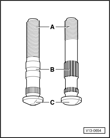
→ Fig.8     Conrod bolt distinguishing features

Rigid bolt

Anti-fatigue bolt

A - Thread

M9x1

M8x1

(15 mm long)

(25 mm long)

B - Centre section

Toothed

Smooth

C - Shape of head

Half round

Conical

 
U13-0020

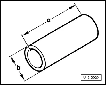
→ Fig.9     Piston pin distinguishing features

Engine codes

Dimension (mm)

FB, FD, FH, FN, FP, FT, FK, FV, GH, EM ä07.81, FR ä 05.81

63

22

EM 08.81 ä , FR 06.81 ä, HM

55

22

EW, EX, HN, ä 06.85

54

20

EW, EX, HN 07.85, ä RE

57

20

 
U13-0021

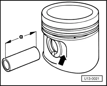
→ Fig.10     Piston with short piston pin

With a = 55 m piston pin the piston was flattened off in the area of the piston pin bore -arrow-.

Note:

When performing repairs, an engine may only be fitted with pistons and piston rings of the same desing and piston from the same weight class.

Piston and cylinder dimensions > < Subsequent machining of ignition timing notch