volkswagen Workshop Repair Guides

Volkswagen Golf Workshop Service & Repair Manuals

Vacuum connections (engine code: EG) > < Basic throttle valve setting
K-Jetronic/Ignition system
K-jetronic injection system
Checking regulated exhaust system (engine code: JH)

Notes for vehicles 08.87 ▸:

The follow components which improve acceleration during the warm-up phase, can be retrofitted:

  • ◆ Diagram pressure switch -F93-,
  • ◆ Idling switch -F60- =>page 25-57 .
 
V97-0042

→ Relay locations

Relay location 2:

  • ◆ Fuel pump relay (65) -J17-.
 
V97-0042

→ Relay locations 13 to 18, the following relays as required:

  • ◆ Current supply relay (26) -J16- for regulated exhaust control unit -J21-.
  • ◆ Relay (53) -J199- for cold start enrichment on vehicles with diaphragm pressure switch (gradually introduced form 08.87)
  • ◆ Frequency relay (37) -J95- for cold start valve, USA and Japan only
  • ◆ Control unit (57) -J143- or can be marked 1 green/brown for two-way valve for idling speed boost

( ) = Production control number

Checking Lambda regulation thermoswitch -F58-

 
V25-1079
  • ‒ → Check resistance at thermoswitch contacts -A-. If necessary, cool off with chilling spray.

Part Nº.

Specification

035919369D

adobe 25 °C

∞ω

bellow 15 °C

max. 0.5ω

027919369B

adobe 47 °C

∞ω

bellow 15 °C

max. 0.5ω

035919369B

adobe 40 °C

∞ω

bellow 30 °C

max. 0.5ω

Connect tester V.A.G 1367

 
V25-1138
  • ‒ → To measure the duty cycle connect V.A.G 1367 to plug -1- (blue/white wire) and press "[nvlt ] %" button. Only use measuring cable V.A.G 1367/5 if the plug -1- has round sleeves.

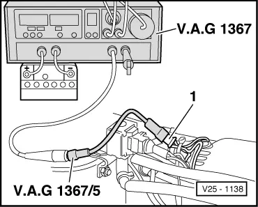
Notes:

On the Scirocco the connector -1- is located near the ignition coil on the wiring loom.

Attention!
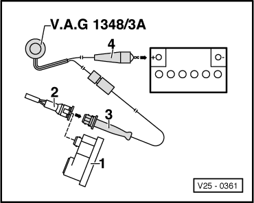
The cable clamp for N

Connect remote control V.A.G 1348/3A

 
V25-0361
  • ‒ → Pull plug -2- off warm-up -1- and connect with connector -3- of the remote control.
  • ‒ Connect crocodile clip -4- to battery (+).

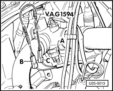
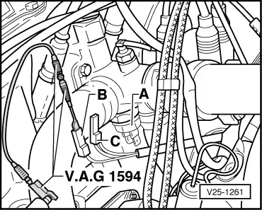
Checking frequency valve

  • ● Fuse Nº. 5 OK.
  • ● Remote control V.A.G 1348/3A connected =>page 25-89
  • ‒ Operate remote control switch.
         Frequency valve must click audibly.

If the valve clicks the check is completed.

 
V25-0698
  • ‒ → if the does not click, pull connector off frequency valve -arrow- and check frequency valve resistance.
         Specification: 2...3 ω
  • Otherwise renew frequency valve.
  • ‒ If the frequency valve is OK, connect diode test lamp V.A.G 1527 to plug using aux. cables from V.A.G1594.
  • ‒ When the remote control is operated, the LED must light up.
  • ‒ If LED does not light up, reconnect plug to frequency valve and check voltage supply to valve.
  • Golf =>page 01-5 , test steps 1 and 2,
  • Scirocco =>page 01-8 , test steps 1 and 2.

If the voltage supply is OK, renew control unit -J21-.

Checking emergency running function of control unit

  • ● Frequency valve -N7- OK, checking =>page 25-90 .
  • ‒ Connect up test appliance V.A.G 1367 and remote control V.A.G 1348/3A for checking duty cycle =>page25-89 .
 
V25-1079
  • ‒ → Pull connector -B- and -C- off thermo switch -A-.
  • ‒ Operate remote control and check duty cycle.
         Specification: 50 ± 2%
  • Otherwise renew control unit -J21-.

Checking full throttle enrichment of the control unit

  • ● Frequency valve -N7- OK, checking =>page 25-90 .
  • ‒ Connect up test appliance V.A.G 1367 and remote control V.A.G 1348/3A to check duty cycle =>page 25-89 .
 
V25-1079
  • ‒ → Pull connector -B- and -C- off thermo switch -A-.
  • ‒ Operate remote control and Full throttle switch -F81- and check duty cycle.
         Specification: 65 ± 2%

If not:

  • ‒ Locate and eliminate open circuit.
  • Golf =>page 01-7 , test steps 7,
  • Scirocco =>page 01-10 , test steps 6.
  • ‒ Checking full throttle switch -F81- =>page 25-70 .

If no open circuit is present and the full throttle switch is OK, replace control unit -J21-.

Checking Lambda regulation function of the control unit

 
V25-1079
  • ● Frequency valve -N7- OK, checking =>page 25-90
  • ‒ Connect up test appliance V.A.G 1367 and remote control V.A.G 1348/3A to check duty cycle =>page 25-89
  • ‒ → Pull connectors -B- and -C- off thermo switch -A-.
 
U25-0012
  • ‒ → Separate Lambda probe wire connector and hold connector -1- to earth -A-.
  • ‒ Operate remote control and check duty cycle.
         Specification: above 87 % rising
  • ‒ Connect plug -1- of the probe wiring to a 1.5 V battery (+) -B- and the battery (-) to earth.
  • ‒ Operate remote control and check duty cycle.
         Specification: bellow 20 % falling

If not:

  • ‒ Locate and eliminate open circuit.
  • Golf =>page 01-6 , test steps 5,
  • Scirocco =>page 01-9 , test steps 4.

If no open circuit is present, replace control unit -J21-.

Checking cold running enrichment function of the control unit -J21-

 
U25-0013
  • ● Frequency valve -N7- OK, checking =>page 25-90
  • ‒ Connect up test V.A.G 1367 and remote control V.A.G 1348/3A to checking duty cycle =>page 25-89 .
  • ‒ → Pull connectors -B- and -C- off thermo switch -A-.

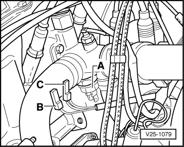
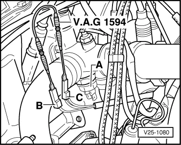
▸07.88 Version with one wire on connector -C-

 
U25-0013
  • ‒ → Bridge connectors -B- and -C- with aux. cables form V.A.G 1594. Operate control and check duty cycle.
         Specification: 80 ± 2%

08.87▸Version with two wires on connector -C-

 
V25-1261
  • ‒ → Connect connector -B- (brown/red wire) to earth (-) using aux. cables from V.A.G 1594. Operate remote control and check duty cycle.
         Specification: 65 ± 2%
  • ‒ If the specification ( dependent upon version) is not attained, locate and eliminate open circuit.
  • Golf =>page 01-6 , test steps 6,
  • Scirocco =>page 01-9 , test steps 5.

If no open circuit is present, replace control unit -J21-.

Checking cold running enrichment function though the vacuum switch -F128-

(Only on version with two wires on connector -C- from thermo switch)

 
V25-1080
  • ‒ → Bridge connectors -B- and -C- with aux. cables from V.A.G 1594.
  • ‒ Separated Lambda probe wiring connector.
  • ‒ Start engine and check duty cycle at idling.
 
U25-0014
  • ‒ → Vacuum pipe -2-:
         connected: 65 ± 2%
         disconnected: 50 ± 2%
  • ‒ Connector -3-:
         connected: 65 ± 2%
         disconnected: 50 ± 2%
 
U25-0014

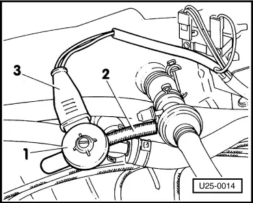
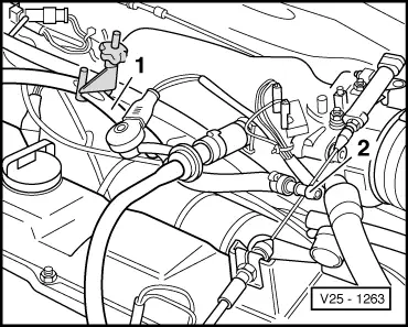
→ If only 50 ± 2% or only 65 ± 2% is indicated, pull connector -3- off vacuum switch -1- and check duty cycle at idling speed.

  • Terminals on connector -3-
    not bridged = 50 ± 2%
  • Terminals on connector -3-
    bridged = 65 ± 2%

If OK, The vacuum switch -1- -F128- or the vacuum pipe -2- is defective.

If the specifications are not attained, locate and eliminate open circuit or short circuit in wiring to vacuum switch -F128- using CFD

Checking cold start enrichment function of control function -J21-

 
V25-1080

→ (Only on version with two wires on connector -C- from thermo switch)

  • ‒ Frequency valve -N7- OK, checking =>page 25-90 .
  • ‒ Connect tester V.A.G 1367 to check duty cycle =>page 25-88 .
  • ‒ Pull H.T cable form the coil out the distributor and earth (-) with aux. cable from V.A.G 1594.
  • ‒ Bridge connect -B- and -C- with aux. cable from V.A.G 1594.
  • ‒ Check duty cycle when starting.
         Specification: 65 ± 2%

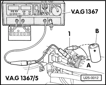
If a duty cycle of 50 % is indicated, locate and eliminate open circuit for relay 53 -J199- using current flow diagram.

If no open circuit is found, replace relay 53 for cold start enrichment -J199-.

Checking Lambda probe -G39-

  • ● Engine oil temperature min 80 °C.
  • ● Idling adjustment OK, checking =>page 25-36
  • ● Lambda regulation function of control unit -J21- OK, checking =>page 25-93
  • ‒ Connect tester V.A.G 1367 to check duty cycle =>page 25-88 .
  • ‒ Start engine and allow to idle for at least 2 minutes.
 
V25-1263
  • ‒ → Clamp-off -1- from two-way valve -N62- for idling speed boost.
  • ‒ Pull off crankcase breather hose -2-.
  • ‒ Seal off opening on hose -2- and watch display on tester.
  • The duty cycle must drop, then alternately rise and fall.

If the duty cycle does not drop, replace lambda probe -G39- (the Lambda probe wiring connect must be connected during the test).

Vacuum connections (engine code: EG) > < Basic throttle valve setting