
Golf Mk3
|
Dismantling and assembling gearbox
Assembly sequence
|
 |
|
|
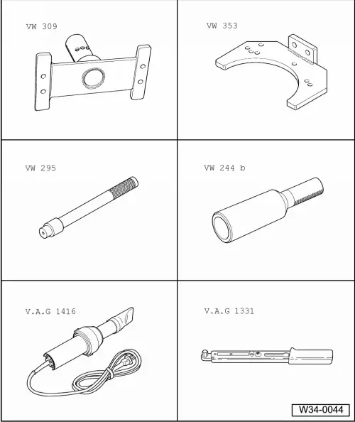
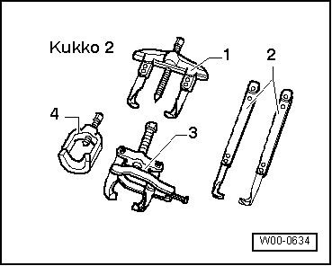
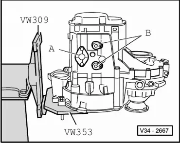
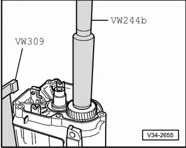
Special tools and workshop equipment required
with Matra V170 hooks |
 |
|
|
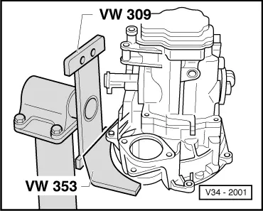
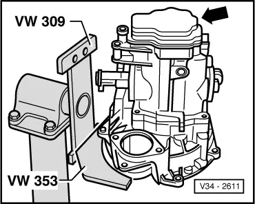
Dismantling
|
 |
|
|
 |
|
|
 |
|
 |
|
|
 |
|
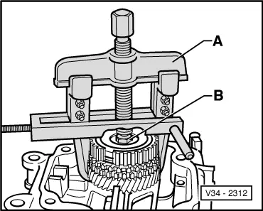
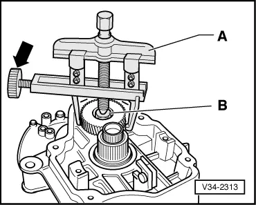
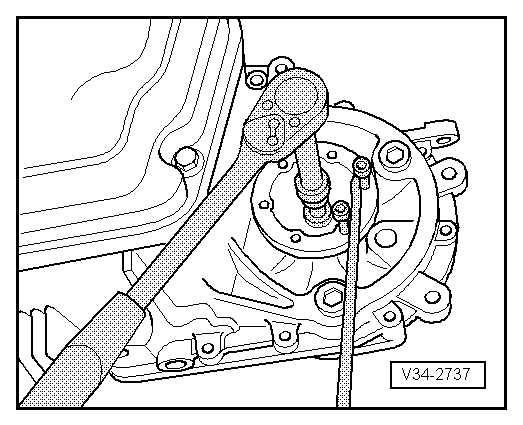
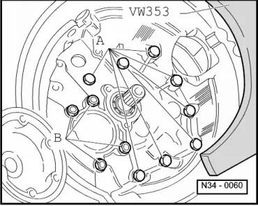
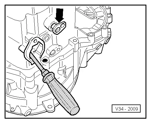
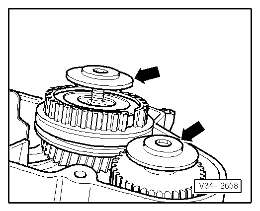
Note: When pulling off the gear wheel ensure that the hooks do not bend outwards, if necessary tighten screw (arrow). After 5th gear wheel has been removed check for damage. |
 |
|
|
 |
|
 |
|
|
 |
|
|
 |
|
|
 |
|
|
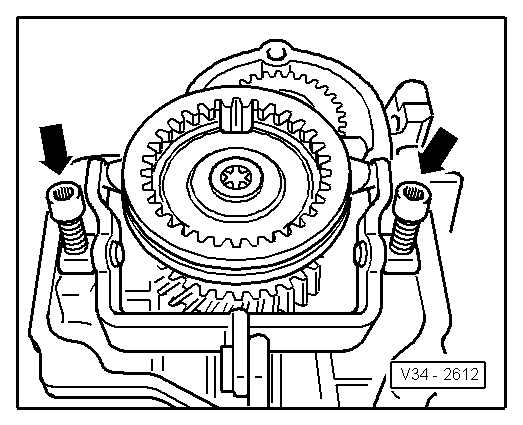
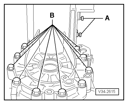
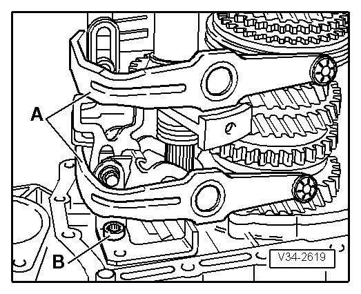
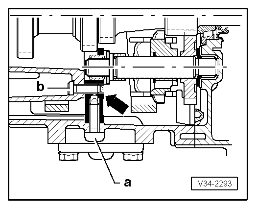
Note: Do not remove nuts -B- for output shaft bearing support. |
 |
|
|
 |
|
 |
|
Assembling
|
 |
|
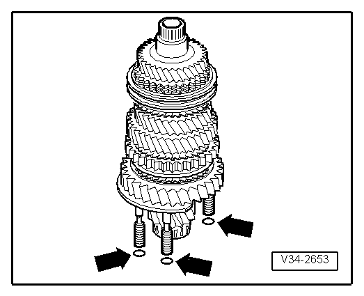
Note: The illustration only shows 3 of the 4 sealing rings.
|
 |
|
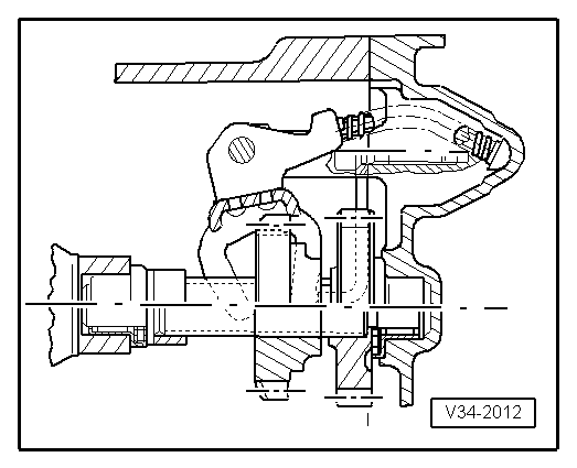
→ Installation position reverse gear
|
 |
|
Note: The selector segments must be positioned in the grooves on the locking collars.
|
 |
|
|
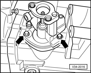
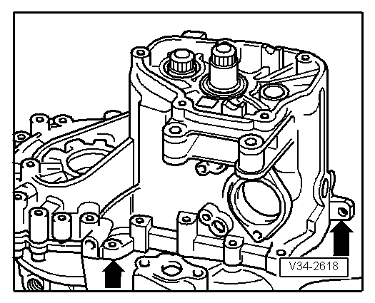
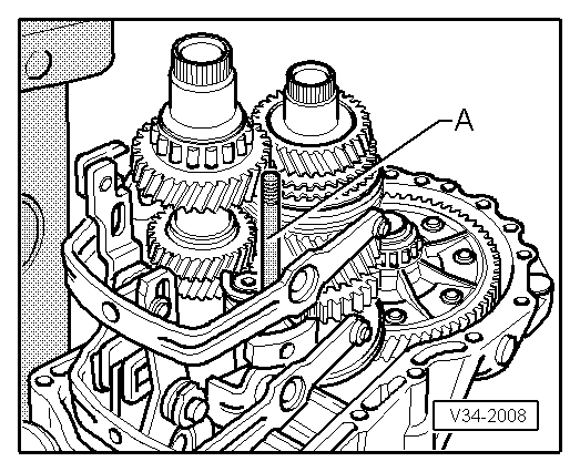
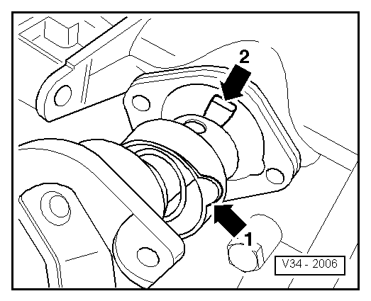
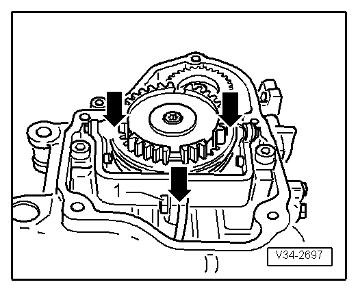
Install reverse shaft support bolts (arrow) as follows:
|
 |
|
|
 |
|
|
→ Install selector shaft as follows:
|
 |
|
|
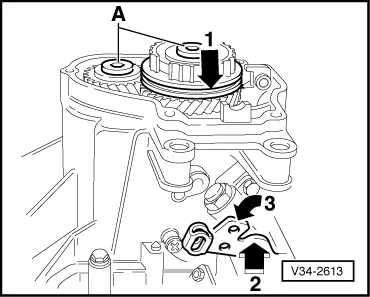
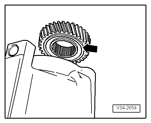
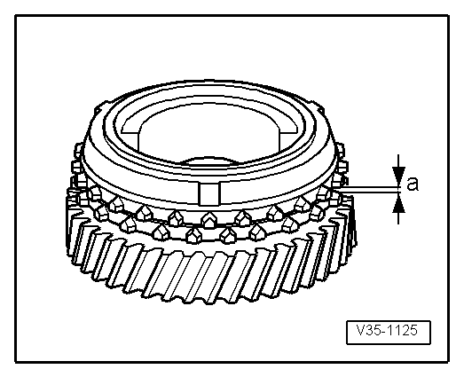
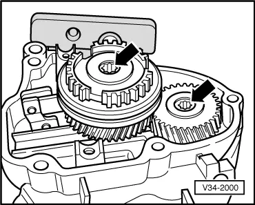
→ Installation position 5th gear wheel The circumferential groove (arrow) faces to gearbox housing. |
 |
|
|
 |
|||||||
|
Checking 5th gear synchro-ring
|
 |
|
|
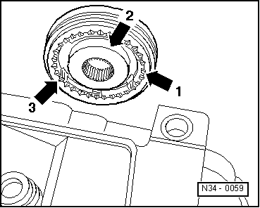
→ Installation position 5th gear synchro-hub/locking collar The pointed teeth of the locking collar (arrow 1) and the high shoulder of the synchro-hub (arrow 2) face the gearbox housing. The syncro-hub mountings (arrow 3) align with the synchro-ring cast locking pieces (=>arrows on Illustration N35-0018, Page 34-78 ). |
 |
|
|
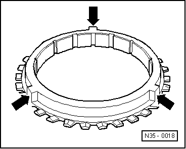
→ 5th gear synchro-ring with cast locking pieces (arrows) |
 |
|
|
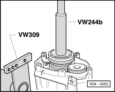
Note: When driving on ensure synchro-ring is free to move. |
 |
|
|
|
|