volkswagen Workshop Repair Guides

Volkswagen Workshop Service and Repair Manuals

Dismantling and assembling parking lock > < Dismantling and assembling 3rd and 4th gear clutch -K3- with turbine shaft
Automatic gearbox 01M - from 01.95
Removing and installing valve chest
 
N38-0036
Warning!
Do not run engine or tow vehicle with oil pan removed or when there is no ATF in gearbox.
  • ◆ The valve chest or the conductor strip can also be removed when the gearbox is installed.

The conductor strip can be removed individually.

    • ‒ Remove starter motor on vehicles with 6-cyl. engine to do this.
  • ◆ After re-installing the oil pan, fill with ATF .
  • ◆ Always replace a valve chest which is fouled or defective.
  • Plug
    • ◆ Always renew seal =>Fig.2
    • ◆ Checking ATF level and topping-up => Page 37-55
 
N38-0036
  • Overflow pipe
    • ◆ Remove to drain ATF => Fig. 1
    • ◆ Screw in onto stop
    • ◆ Checking ATF level and topping-up => Page 37-55
  • Oil pan
  • Bolt, 12 Nm
  • Magnet
    • ◆ Insert in the recess in oil pan
  • Spacer bush
    • ◆ Press into gasket
  • Gasket
    • ◆ Always replace
    • ◆ Press spacer bushes into gasket
  • ATF screen
    • ◆ Installing =>Fig.10
  • Bolt, 5 Nm
 
N38-0036
  • Gasket
    • ◆ Always replace
    • ◆ Insert in valve chest
  • Valve chest
    • ◆ Removing => Fig. 4
    • ◆ Installing => Fig.9
    • ◆ Marking =>Fig.6
    • ◆ Installing seal -item 10 -
  • Bolt, 10 Nm
  • O-ring
    • ◆ For cable transition piece
    • ◆ Always replace
  • Conductor strip
    • ◆ With cable transition piece and connector
    • ◆ Can be removed and installed with gearbox installed
  • Retaining bracket
    • ◆ Clip with bolt => Fig. 11
 
N38-0036
  • Cable connector
    • ◆ Secure to gearbox housing
  • Clip
    • ◆ Insert the lug of the cable connector in the recess in the clip
    • ◆ Clip with bolt => Fig. 11
  • Nut, 10 Nm
    • ◆ Clip with bolt, 20 Nm => Fig. 11
  • Plug for solenoid valves
    • ◆ Pull off solenoid valves with 3373 => Fig. 3
  • Sealing plug
    • ◆ Take out before removing and installing free wheel
    • ◆ Insert so that the lug is located in the groove on housing
      =>Fig.5
    • ◆ Place O-rings onto sealing plug
 
N38-0036
  • O-ring
    • ◆ Always replace
  • O-ring
    • ◆ Always replace
  • Operating rod for manual selector valve
    • ◆ Unhooking => Fig. 4
    • ◆ Install with stepped side facing manual selector valve =>Fig.7
    • ◆ Adjusting =>Fig.8
 
N38-0030

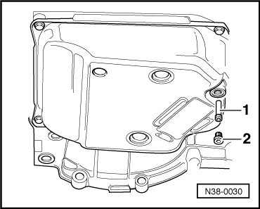
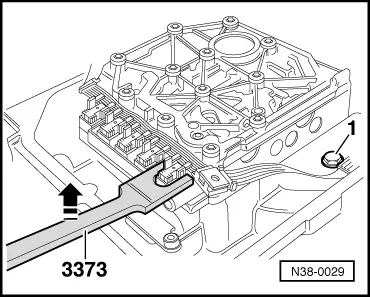
→ Fig.1     Draining ATF

  • ‒ Place container under the gearbox.
  • ‒ Remove plug -2-.
  • ‒ Remove overflow pipe -1- and allow ATF to drain.
  • ‒ Screw overflow pipe in onto stop.
 
N38-0037

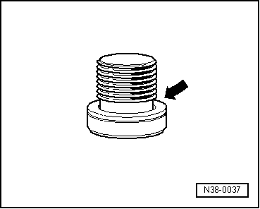
→ Fig.2     Replacing plug seal

  • ‒ Cut open seal -arrow- with side cutting pliers, always renew seal.
  • ‒ After repairs fit new seal to plug and screw in hand-tight when filling with ATF.
  • ‒ Fill with 3 litres of ATF then check ATF level and top-up => Page 37-55 .
 
N38-0029

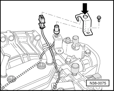
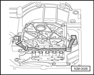
→ Fig.3     Removing conductor strip

  • ‒ Place 3373 onto stop under the solenoid valve plug.
  • ‒ Pull plug off with 3373 in direction of arrow.
  • ‒ Remove bolt -1-.
 
N38-0031

→ Fig.4     Removing valve chest/unhooking operating rod

When removing the valve chest the manual selector valve -1- remains in valve chest.

  • ‒ Shift selector lever/shaft into position "1".
  • ‒ Pull manual selector valve out until it is just possible to unhook the operating rod -2-.
  • ‒ Secure manual selector valve so that it cannot fall out.
 
N38-0025

→ Fig.5     Inserting sealing plug

Pull sealing plug out of housing before removing and installing free wheel otherwise the sealing plug and the O-ring will be damaged.

  • ‒ Fit O-rings to sealing plug.
  • ‒ Insert sealing plug in hole in gearbox housing -arrow-.
 
N38-0028

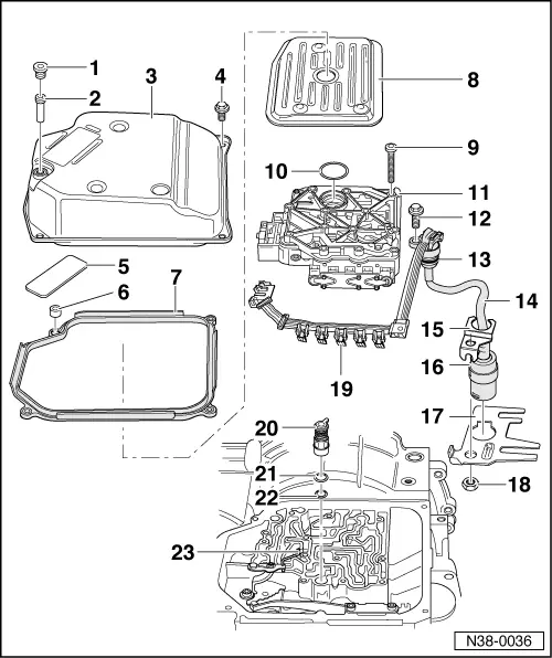
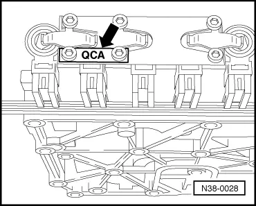
→ Fig.6     Identification of valve chest

Code letters are stamped on a metal tab. Metal tab must remain on the valve chest.

Allocation valve chest/gearbox =>from Page 00-5

 
N38-0031

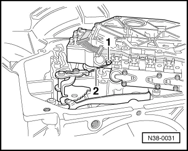
→ Fig.7     Hooking operating rod onto manual selector valve

  • ‒ Turn manual selector valve -1- so that the shoulder is to operating rod.
  • ‒ Guide operating rod -2- with manual selector into valve body.
 
V38-0709

→ Fig.8     Adjusting operating rod for manual selector valve

  • ‒ Move selector shaft to position "P".
  • ‒ Push operating rod with manual selector valve into valve body as far as the stop (direction of arrow) and tighten bolt to 4 Nm.
  • ◆ Manual selector valve must always be resting against the stop. Counter-hold in direction of arrow when tightening bolt.
  • ◆ Always replace bolt and manual selector valve retaining clip.
 
N38-0026

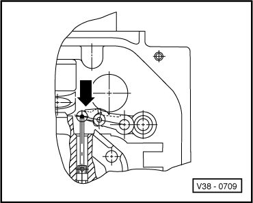
→ Fig.9     Installing valve body

  • ‒ Route conductor strip as illustrated, when installing do not kink or twist.
 
N38-0027

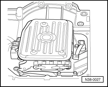
→ Fig.10     Installing ATF screen

  • ‒ Before installing the ATF screen insert seal in the valve body.
  • ‒ Firmly press ATF screen onto valve body.
 
N38-0075

→ Fig.11     Installing securing clip with bolt for conductor strip connector

  • ‒ Connect conductor strip connector to lower retainer.
  • ‒ Fit upper retainer with recess (arrow) onto connector lug.
  • ‒ Tighten bolt to 20 Nm.

Dismantling and assembling parking lock > < Dismantling and assembling 3rd and 4th gear clutch -K3- with turbine shaft