
Golf Mk3
 Note
Note
|

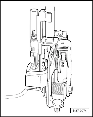
| 1 - | Selector lever |
| q | Assembling → Fig. |
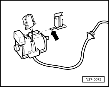
| 2 - | Indicator lighting |
| q | Securing indicator lighting connector (one-piece solenoid with wiring harness) → Fig. |
| q | In right-hand drive vehicles, there is an additional contact that prevents the engine from being started when locking button on “selector lever handle” is pressed. |
| 3 - | Spring |
| 4 - | Push rod |
| q | Grease sliding surfaces |
| 5 - | Guide sleeve |
| q | Fit after installing push rod. |
| 6 - | Set screw |
| q | Always renew |
| q | To remove set screw, remove selector lever lock solenoid -N110- and indicator lighting. Clamp set screw in vice and loosen by turning selector lever. |
| q | Insert with locking fluid -AMV 185 101 A1- |
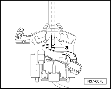
| 7 - | Selector lever lock solenoid -N110- |
| q | May be one part together with wiring harness or harness may be separate part |
| q | Adjusting → Fig. |
| q | Functional check → Fig. |
| q | Securing wiring harness to selector bracket (selector lever lock solenoid -N110- with wiring harness) → Fig. |
| q | Securing wiring harness to selector lever lock solenoid -N110- and indicator lighting → Fig. |
| q | Securing indicator lighting connector → Fig. |
| q | Can be checked in electrical check → Chapter and in measured value block → Chapter |
| 8 - | Bolt, 3 Nm |
| q | Qty. 2 |
| q | Insert with locking fluid -AMV 185 101 A1- |
| 9 - | Nut, 5 Nm |
| q | Always renew |
| 10 - | Washer |
| 11 - | Locking lever |
| q | For ignition key removal lock. |
| q | Adjust together with locking cable → Chapter. |
| 12 - | Spring |
| q | Hook into hole in detent segment |
| 13 - | Support bracket |
| q | For locking cable |
| q | Removing and installing locking cable → Chapter |
| q | Adjusting locking cable → Chapter |
| 14 - | Spring |
| q | For locking pin |
| 15 - | Detent segment |
| q | Assemble selector lever before installing in selector bracket → Fig. |
| 16 - | Locking pin |
| q | with holder |
| 17 - | Hexagon socket head bolt, 6 Nm |
| 18 - | Bolt, 6 Nm |
| 19 - | Washer |
| 20 - | Spring |
| q | Insert in selector lever together with lever → Item |
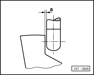
| 21 - | Lever |
| q | For locking in selector lever position “N” or “P” |
| q | Adjusting → Fig. |
| 22 - | Bush |
| 23 - | Nut, 10 Nm |
| q | Always renew |
| 24 - | Flange bolt |
| q | Grease shank |
|
|
|
|
|
|