
Golf Mk3
|
Servicing valve gear
Removing and installing camshafts
Removing
=> Repair group 28; Motronic injection and ignition system; Servicing ignition part
|
 |
|
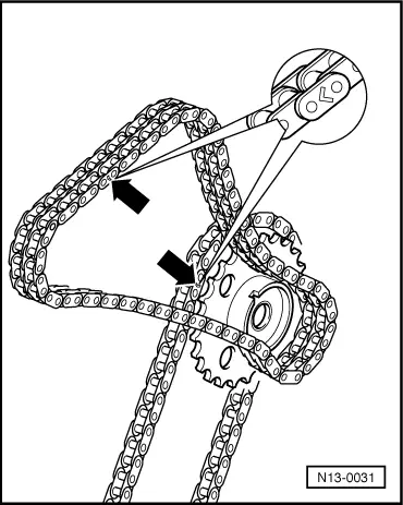
→ Note: Only counter-hold camshaft with 24 mm OJ spanner -arrow-. The camshaft jig 3268 must not be in place when tightening or loosening the chain sprockets.
|
 |
|
Notes:
|
 |
|
|
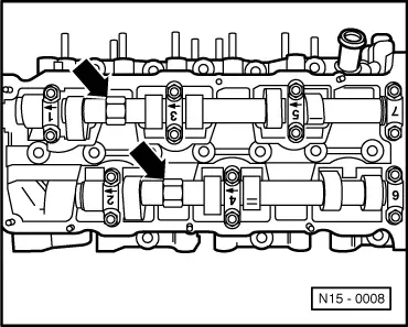
→ Camshaft cylinder bank 1, 3 and 5
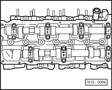
Camshaft cylinder bank 2, 4 and 6
Installing
Notes:
|
 |
|
Camshaft cylinder bank 1, 3 and 5
Camshaft cylinder bank 2, 4 and 6
|
 |
|
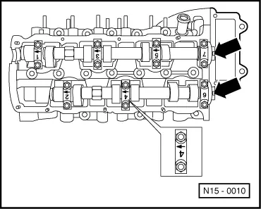
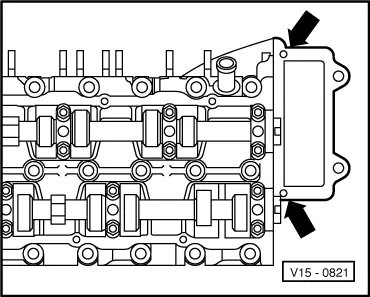
Note: With the cylinder head installed the holes in the cylinder head gasket are only half visible.
Notes:
|