volkswagen Workshop Repair Guides

Volkswagen Workshop Service and Repair Manuals

Assembly overview - Hydraulic unit, right-hand drive > < Notes for repair work on ABS, ABS/EDL
Running gear
Anti-locking brake system (ABS) and anti-locking brake system with electronic differential lock (ABS/EDL) Teves 20 GI
Removing and installing control and hydraulic units

Location:

The control unit is bolted to the hydraulic unit and is located on left in the engine compartment.

 
N45-0039
Warning:
Do not bend the brake pipes in the area of the hydraulic unit!

→ Sealing plugs repair kit

After separating the control unit from the hydraulic unit always fit the valve dome transportation protection on the hydraulic unit.

Warranty claims for hydraulic units on which the valve dome transportation protection was not used, will not be accepted.

  •     1 -    Valve dome transportation protection (plastic foam)
  •     2 -    Sealing plugs M 10
  •     3 -    Sealing plugs M12

Removing:

  • ‒ Obtain radio code on vehicles with coded radio.
  • ‒ Disconnect battery.
  • ‒ Remove coolant expansion tank and swing to side.
 
N45-0041
  • ‒ → Release control unit connector retainer and pull connector off control unit.
  • ‒ Fit bleeder hose and bleeder bottle to the front left brake caliper bleeder screw and open bleeder screw.
  • ‒ Depress brake pedal at least 60 mm.
  • ‒ Fit brake pedal loading device from V.A.G 1238 B.
  • ‒ Close front left bleed screw.
  • ‒ Remove heat shield from tandem master brake cylinder.
  • ‒ Disconnect brake pipes on brake master cylinder and hydraulic unit and seal brake pipes and threaded holes with plugs from repair kit Part No. 1H0 698 311 A.
  • ‒ Remove torx socket head bolt T 25 from hydraulic unit bracket.
  • ‒ Remove hydraulic unit.
  • ‒ Pull connector for hydraulic pump motor off control unit.
 
N01-0019
  • ‒ → Remove bolts from control unit and pull control unit off.

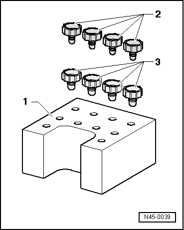
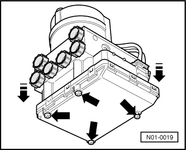
Do not cant control unit when pulling off.

Cover control unit magnetic coils with a lint-free cloth.

After separating control unit/hydraulic unit use transportation protection for valve dome.

Installing:

Notes:

  • ◆ Only remove sealing plugs on new hydraulic unit when the corresponding brake pipe is going to be fitted.
  • ◆ If the sealing plugs are removed too early, brake fluid can escape, it can then no longer be guaranteed that the unit is sufficiently filled or adequately bled.
  • ‒ Using new bolts, bolt control unit to hydraulic unit.
    Observe tightening torque max. 4 Nm.
  • ‒ Fit connector on hydraulic pump motor.
  • ‒ Further installation is carried out in the reverse sequence
  • ‒ Bleed brake system =>Repair group 47
  • ‒ Code control unit =>Booklet, Running gear self-diagnosis

Tightening torques:


For left-hand drive vehicles:


Control unit to hydraulic unit

max.
4 Nm

Torx socket head bolts for hydraulic unit on bracket


8 Nm

Nut for tandem master brake cylinder to brake servo


25 Nm

Heat shield on TMC

8 Nm

Brake pipes to ABS unit:


Thread M 10 x 1

15 Nm

Thread M 12 x 1

15 Nm

For right-hand drive vehicles:


Control unit to hydraulic unit

max.
4 Nm

Nut for hydraulic unit on bracket

10 Nm

Bracket on mounting plate

25 Nm

Brake pipes to ABS unit:


Thread M 10 x 1

15 Nm

Thread M 12 x 1

15 Nm

Assembly overview - Hydraulic unit, right-hand drive > < Notes for repair work on ABS, ABS/EDL