
Golf Mk3
| Repairing drive shaft |
| Drive shafts on vehicles with Plus running gear have shorter and finer splines on the outer joint. A 12-point nut is used to secure to wheel bearing. |
| The splines of the outer joint and the wheel hub are bonded with locking fluid -D 185 400 A2-. |
| Removing and installing drive shaft for vehicles with Plus running gear → Chapter. |
 Note
Note| t | Quantity of grease for vehicles up to 48 kW: 90 g G 6.3 on outside and inside |
| t | Quantity of grease for vehicles with 55 kW and above: |
| t | Outside: 110 g G 6.3 |
| t | Inside: 120 g G 6.3 |
| t | Greasing outer joint: press half of the grease into the joint and the other half evenly into the bellows. |
| t | Greasing inner joint: press half of the grease into the joint from both sides and the other half evenly into the bellows. |
| t | Regrease joint if required when renewing boot. |
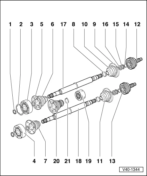
| 1 - | Retaining ring |
| q | Renew |
| q | Remove and install with circlip pliers -VW 161 A-. |
| 2 - | Gasket |
| q | Renew: Pull off protective foil and stick onto joint. Only 100 mm Ø constant velocity joints. |
| Modification |
| q | As of 08.93 also on constant velocity joints with 90 mm Ø. |
| 3 - | Inner constant velocity joint 100 mm Ø for vehicles with output of 55 kW and above |
| q | Renew only complete. |
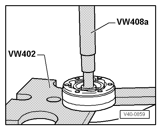
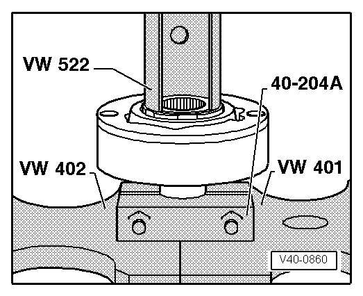
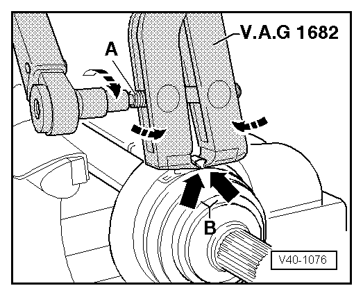
| q | Pressing off → Fig.. |
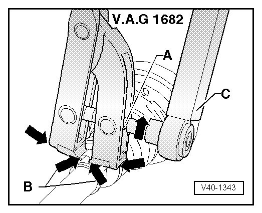
| q | Pressing on → Fig.. |
| q | Greasing → Chapter |
| q | Checking → Chapter |
| 4 - | Inner constant velocity joint 94 mm Ø for vehicles with output up to 48 kW |
| q | Pressing off → Fig.. |
| q | Pressing on → Fig.. |
| q | Greasing → Chapter |
| q | Checking → Chapter |
| 5 - | Dished spring |
| q | Splines in inner diameter. |
| q | Installation position: larger Ø (concave side) contacts constant velocity joint. |
| 6 - | Joint protective boot for 100 mm Ø constant velocity joint |
| q | With vent hole |
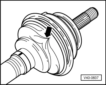
| q | Check for splits and chafing. |
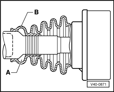
| q | Installation position for left shaft → Fig. |
| q | Installation position for right shaft → Fig.. |
| q | Coat cap with D3. |
| q | Drive off with drift. |
| 7 - | Joint protective boot for 94 mm Ø constant velocity joint |
| q | Check for splits and chafing. |
| q | Drive off with drift. |
| 8 - | Clamp |
| q | Renew |
| q | Tensioning → Fig. and → Fig.. |
| 9 - | Hose clip |
| q | Renew |
| q | Tensioning → Fig. and → Fig.. |
| 10 - | Joint protective boot for 90 mm Ø constant velocity joint |
| q | Check for splits and chafing. |
| q | Allow air to enter joint protective boot briefly to balance pressure before tightening small clamp in place → Fig.. |
| 11 - | Joint protective boot for 81 mm Ø constant velocity joint |
| q | Check for splits and chafing. |
| q | Allow air to enter joint protective boot briefly to balance pressure before tightening small clamp in place → Fig.. |
| 12 - | Outer constant velocity joint 90 mm Ø for vehicles with output of 55 kW and above |
| q | Renew only complete. |
| q | Removing → Fig. |
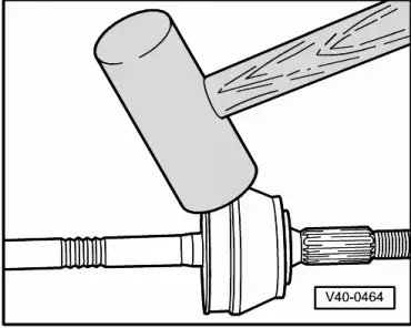
| q | Installing: drive onto shaft with plastic hammer until compressed retaining ring seats. |
| q | Greasing → Chapter |
| q | Checking → Chapter |
| 13 - | Outer constant velocity joint 81 mm Ø for vehicles with output up to 48 kW |
| q | Renew only complete. |
| q | Removing → Fig. |
| q | Installing: drive onto shaft with plastic hammer until compressed retaining ring seats. |
| q | Greasing → Chapter |
| q | Checking → Chapter |
| 14 - | Retaining ring |
| q | Renew |
| q | Insert in groove in shaft. |
| 15 - | Thrust washer |
| 16 - | Dished spring |
| q | Outer Ø (concave side) contacts thrust washer. |
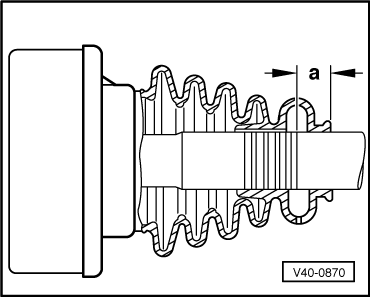
| 17 - | Drive shaft for vehicles with output of 55 kW and above |
| q | Constant velocity joint splines 4 mm longer than shafts for lower-output engines, measured from dished spring support to retaining ring groove. |
| 18 - | Drive shaft for vehicles with output up to 48 kW |
| 19 - | Damper weight |
| q | Installation position → Fig.. |
| 20 - | Constant velocity joint boot 94 and 100 mm Ø |
| q | Fitted as of 01.93. |
| 21 - | Hose clip |
| q | Tightening → Fig.. |
|
|
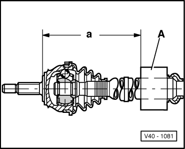
| Dimension “a” mm | Engine |
| 541 ± 1 | 1.8 l - 55 kW |
| 1.8 l - 66 kW | |
| 1.9 l - 48 kW | |
| 1.9 l - 55 kW | |
| 2.0 l - 85 kW | |
| 2.0 l - 110 kW | |
| 525 ± 1 | 1.9 l - 47 kW |
| 1.9 l - 66 kW |
|
|
Note
|
|
Note
|
|
|
|
|
|
Note
|
|
|
|