volkswagen Workshop Repair Guides

Volkswagen Workshop Service and Repair Manuals

Removing and installing drive shaft, vehicles with automatic gearbox > < Reworking cap nut in side member
Running gear
Servicing front suspension (Base running gear)
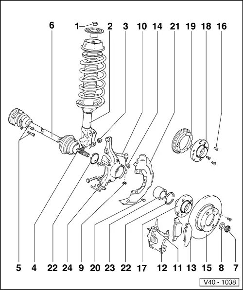
Removing and installing wheel bearing, suspension strut and drive shaft (Base running gear)
 
V40-1038

Notes:

  • ◆ If a vehicle has to be moved after removing the drive shaft, first install outer joint and tighten to 50 Nm otherwise the wheel bearing will be damaged.
  • ◆ It is not permitted to carry out welding and straightening operations on load bearing suspension components or those components which locate the wheels.
  • ◆ Always renew self-locking nuts.
  • ◆ Always renew corroded nuts/bolts.
  • ◆ Wheel bolt tightening torque: 110 Nm.
 
V40-1038
  • Self-locking nut, 60 Nm
    • This nut is loosened when the suspension strut is unbolted at body/suspension turret.
    • After each loosening of the hexagon nut it is imperative that the slotted nut on the suspension strut mounting isretightened to 40 Nm!
    • ◆ Loosening and tightening
      => Fig.1
  • Suspension strut
    • ◆ Dismantling and assembling
  • Self-locking nut, 95 Nm
  • Bolt
    • ◆ Adjusting camber
      => Page 44-4
    • ◆ Mark position before loosening
  • 45 Nm
 
V40-1038
  • Drive shaft
    • ◆ To remove and install separate ball joint/wishbone connection => Fig.2
    • ◆ Repairing => Page 40-68
  • Self-locking nut, 265 Nm
    • ◆ Only loosen and tighten with the vehicle standing on its wheels (danger of accident)
    • ◆ Any paint residue and/or corrosion on the thread of the outer joint must be removed before the nut is fitted
  • Washer
  • Self-locking nut, 35 Nm
  • Track rod
    • ◆ Removing and installing
      => Page 48-47
 
V40-1038
  • Hexagon bolt, 25 Nm
  • Brake caliper
    • ◆ Do not loosen brake hose when working on front suspension
    • ◆ Hang up with wire or similar
  • Brake pads
    • ◆ Removing and installing
  • 50 Nm
  • Brake disc
  • Cross-head screw
  • Hub
    • ◆ Pressing out =>Fig.3
    • ◆ Pressing in =>Fig.7
    • ◆ Pulling off bearing inner race
      =>Fig.4
 
V40-1038
  • Hub
    • ◆ For vehicles with ABS
    • ◆ Pressing out =>Fig.3
    • ◆ Pressing in =>Fig.7
  • Speed sensor rotor
    • ◆ Only on vehicles with ABS
  • Hexagon bolt, 10 Nm
  • Splash plate
  • Circlip
    • ◆ Ensure correctly seated
  • Wheel bearing
    • ◆ Pressing out =>Fig.5
    • ◆ Renew, as it is destroyed during pressing out
    • ◆ Pressing in =>Fig.6
  • Wheel bearing housing
 
V40-1070

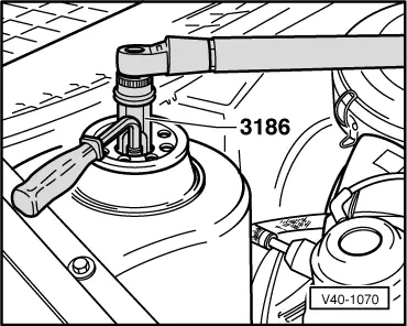
→ Fig.1    Removing and installing suspension strut to body

 
N40-0179

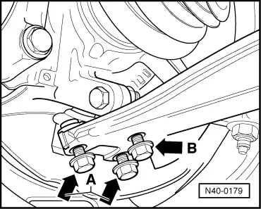
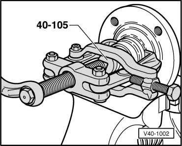
→ Fig.2    Separating ball joint/wishbone connection

  • ‒ Remove bolts (arrow A).
  • ‒ Loosen bolt (arrow B).

Note:

First mark installation position

 
V40-1035

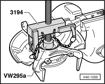
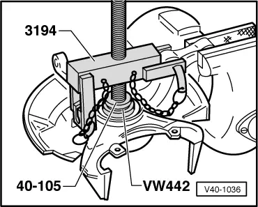
→ Fig.3    Pressing hub out of wheel bearing housing

 
V40-1002

→ Fig.4    Pulling bearing race out of hub

Only use puller with leg clamp e.g. Kukko 204-2 (commercial type).

 
V40-1036

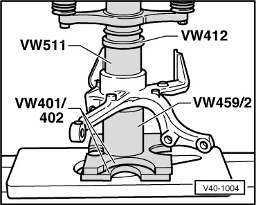
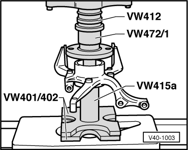
→ Fig.5    Pressing wheel bearing out of wheel bearing housing

 
N40-0127

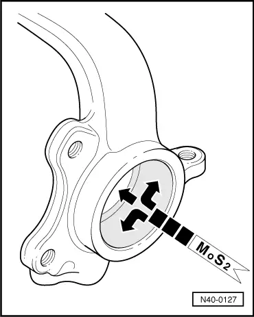
→ Coat hole completely with Molykote grease.

 
V40-1004

→ Fig.6    Pressing wheel bearing into wheel bearing housing

 
V40-1003

→ Fig.7    Pressing hub into wheel bearing

Removing and installing drive shaft, vehicles with automatic gearbox > < Reworking cap nut in side member