
Golf Mk4
|
Dismantling and assembling output shaft
From gearbox build date 02 05 0 the synchronisation for 1st gear has been modified
|
 |
|
|
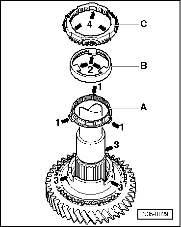
→ The following components have been added or modified:
with additional recesses -4- for the lugs -1- of inner ring -A-.
with additional recesses -3- for the lugs -2- of outer ring -B-. Note: For the 2nd gear the same inner ring, outer ring and synchro ring are installed.
|
|
|
|
→ Installation position of inner ring, outer ring and synchro-ring 1st gear:
Angled lugs (arrow 1) point towards outer ring -B-.
Lugs (arrow 2) engage in gear wheel recesses (arrow 3).
The recesses (arrow 4) engage in lugs (arrow 1) of inner ring -A-. |
 |
|||||||
|
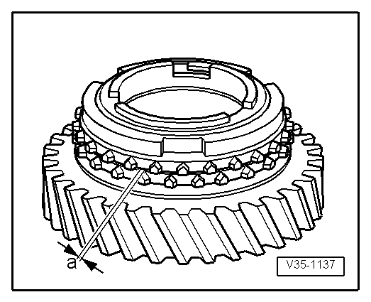
→ Check inner ring 1st gear for wear
|
 |
|||||||
|
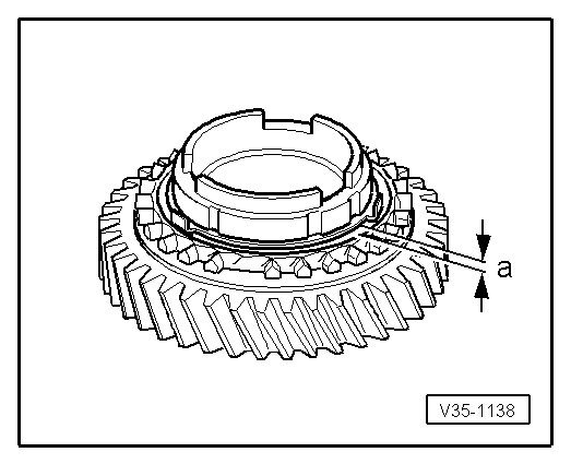
→ Check synchro-ring 1st gear and outer ring for wear
|
 |
|
|
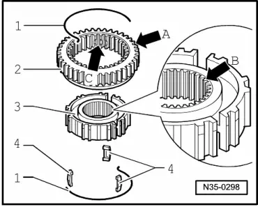
→ Assembling locking collar and locking pieces with 1st and 2nd gear synchro-hub
With introduction of the modified 1st gear synchronisation the shoulder has the same width on both sides of synchro-hub. The shoulder has a chamfer on one side (arrow B). After assembly the shoulder of the synchro-hub and the outer splines of the locking collar (arrow A) face same direction. Recesses for locking pieces on synchro-hub and locking collar (arrow C) must align. |
 |
|
|
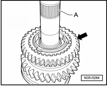
→ Installation position of locking collar/synchro-hub 1st and 2nd gear The locking collar splines (arrow) point to splines for 3rd/4th gear synchro-hub -A-.
|