Power transmissionServicing clutch release mechanism
|
Servicing clutch release mechanism
Servicing clutch release mechanism
|
| |
|
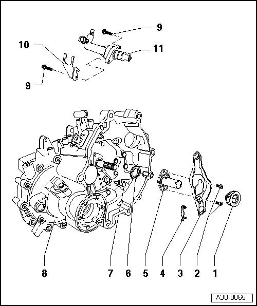 |
- Release bearing
-
◆ Remove and install together with clutch release lever -item 3- and guide sleeve -item 5- => Fig.1
to Fig.3
-
◆ Do not wash-out bearing, only wipe
-
◆ Renew noisy bearings
- Bolt, 5 Nm and turn 90° further
- Clutch release lever
-
◆ Remove and install together with release bearing -item 1- and guide sleeve -item 5-
=> Fig.1
to Fig.3
-
◆ Lubricate grease surface which contacts ball head pin with MoS2
- Retaining spring
-
◆ Secure to clutch release lever
|
| |
|
|
- Guide sleeve
-
◆ Remove and install together with release bearing -item 1- and clutch release lever -item 3- => Fig.1
to Fig.3
- Input shaft oil seal
- Ball stud, 20 Nm
-
◆ Lubricate with MoS2 grease
- Gearbox
- Hexagon bolt, 20 Nm
- Bracket
- Slave cylinder
-
◆ Removing and installing
=> page 30-19
-
◆ Grease end of plunger with MoS2 grease
|
| |
|
 |
|
→
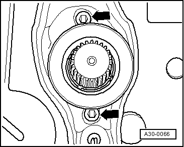
Fig.1
Removing and installing clutch release lever with release bearing and guide sleeve
-
‒ Remove bolt -arrows-.
-
‒ Pull off clutch release lever with release bearing and guide sleeve from input shaft and ball stud.
Installation is performed in the reverse order.
|
| |
|
 |
|
→
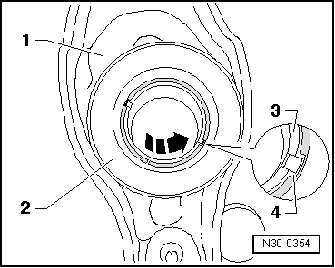
Fig.2
Removing and installing guide sleeve
-
‒ Press guide sleeve -3- upwards out of release bearing -2-.
-
‒ Turn guide sleeve -3- approx. 90° in direction of arrow against release bearing -2- until locking lugs of guide sleeve locate in the grooves -4- of the release bearing.
-
‒ Pull guide sleeve out of release bearing in this position.
Installation is performed in the reverse order.
|
| |
|
 |
|
→
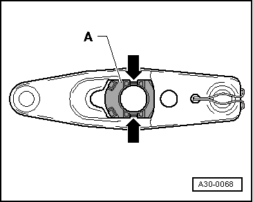
Fig.3
Removing and installing release bearing
-
‒ Press locking lugs -arrows- together on reverse side of clutch release lever and remove release bearing -A- out of clutch release lever.
-
‒ To install, press release bearing -A- in clutch release lever until locking lugs -arrows- locate.
|
05 Transmission