volkswagen Workshop Repair Guides

Volkswagen Workshop Service and Repair Manuals

Supporting engine in installation position > < Removing and installing engine support (Golf, Golf Cabrio, Passat)
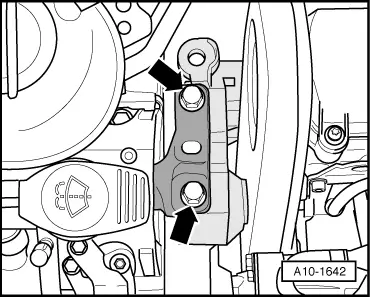
Adjusting assembly mounting (Golf, Passat, Touran)
Procedure
  WARNING
When doing any repair work, especially in the engine compartment, pay attention to the following due to the cramped conditions:
t  Route lines of any kind so that the original routing can be restored.
t  Ensure that there is sufficient clearance to all moving or hot components.
–  Remove engine cover panel → Chapter.
–  Remove air filter housing → Chapter.
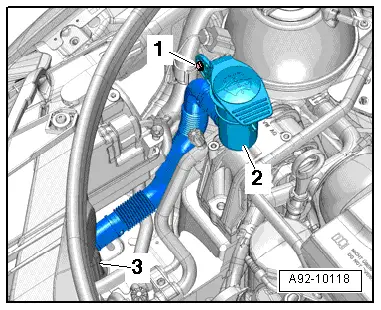
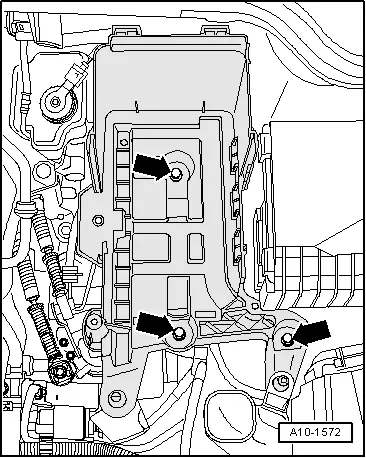
–  Remove intake hose between air mass meter -G70- and intake connecting pipe.
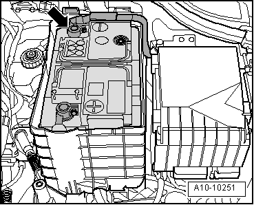
  Caution
To prevent damage to the electronic components when disconnecting the battery:
Observe notes on procedure for disconnecting the battery.
   
–  Disconnect earth wire -arrow- from battery with ignition switched off → Electrical system; Rep. gr.27.
  A10-10251
–  Remove battery and battery tray -arrows-.
(Golf Plus, Touran)
–  Remove plenum chamber bulkhead → General body repairs; Rep. gr.50.
All other vehicles continued
  A10-1572
–  Remove bolt -1-.
–  Push washer fluid reservoir filler pipe with filler neck -2- to side.
  Note
t  Disregard -item 3-.
t  For reasons of clarity, diagram shows installation position with removed fuel filter.
  A92-10118
–  Free air guide hose at retainer -2-.
–  Pull retainer for fuel lines off upwards -arrow- and lay to side.
–  Disconnect electrical connector -3-.
–  Unscrew bolts -1-, remove retainer and lay to side.
  A26-10877
–  Loosen bolt -1-.
–  Unscrew bolt -2- and nut -3-.
–  Take hose retainer -4- off fuel filter, place fuel filter -7- aside (fuel hoses -5- and -6- remain connected).
–  Set up support bracket -10 - 222 A- with necessary adapters as illustrated and support engine in installation position.
t  (Golf, Passat) → Chapter
t  (Golf Plus) → Chapter
t  (Touran) → Chapter
  Note
The securing bolts for the assembly mountings may only be removed if the engine is supported with support bracket -10-222 A-. → Chapter
  A20-10395
–  Unscrew engine support bolts -arrows- in succession and renew (if not already carried out on installing engine).
–  First screw bolts in loosely.
  A10-1642
–  Renew gearbox mounting bolts -arrows- in succession (if not already carried out) and screw in hand-tight.
–  First screw bolts in loosely.
Engine mounting
  A10-1634
–  Using assembly lever between engine support and support arm -1-, adjust position of engine until specifications listed below are obtained:
l  There must be a distance of -a- = 13.5 mm between engine support -2- and right longitudinal member.
l  The side of the engine support casting -2- must be aligned parallel to the support arm -1- (dimension -x- must be identical on both sides).
  Note
Distance -a- = 13.5 mm can be checked with a metal rod of suitable size, or similar.
–  Tighten engine support bolts.
Gearbox mounting
  A10-1687
–  On the gearbox side, ensure that the edges of the support arm -2- and gearbox support -1- are parallel.
l  Dimension -x- must be identical on both sides of mounting.
–  Tighten bolts for gearbox mounting.
l  Specified torques → Chapter.
The remaining installation steps are carried out in the reverse sequence. In the process, note the following:
l  Ensure that fuel lines are tight.
l  Do not interchange supply line and return line (return line blue or with blue marking, supply line black).
–  Observe notes after connecting battery → Electrical system; Rep. gr.27.
  A10-1662

Supporting engine in installation position > < Removing and installing engine support (Golf, Golf Cabrio, Passat)