volkswagen Workshop Repair Guides

Volkswagen Workshop Service and Repair Manuals

Removing and installing timing chain and chain drive for oil pump > < Checking valve timing
Adjusting valve timing
   
Adjusting valve timing
Special tools and workshop equipment required
t  Dial gauge -VAS 6079-
t  Puller -T10094 A-
t  Dial gauge adapter -T10170- or dial gauge adapter -T10170 A-
t  Camshaft clamp -T10171 A-
t  Counterhold tool -T10172-
t  Locking pin -T40011-

   
t  Torque wrench -V.A.G 1601-
t  Counterhold tool -3415-
t  Locking pin -T10340-
t  Torque wrench (5…50 Nm) -V.A.G 1331-

   
t  Spark plug socket and extension -3122 B-

Procedure
–  Drain coolant → Chapter.
   
–  Remove securing bolts -1- from engine cover panel.
–  Detach coolant hoses -2- at engine cover panel and pull engine cover panel upwards.
  N15-10372
–  Pull coolant hoses off coolant pipe -1- and unscrew coolant pipe from camshaft housing and from cylinder block from below.
  N15-10373
–  Release and pull off connector -2-.
–  Remove oil pressure switch -F1--1-.
–  Remove valve timing housing → Chapter.
  N15-10696
–  To turn crankshaft, reinstall bearing bush, crankshaft pulley -2- and crankshaft bolt -3- and securely tighten crankshaft bolt (use counterhold 3415).
–  Remove spark plug from No. 1 cylinder. Use puller -T10094 A- and spark plug socket and extension 3122 B → Chapter.
  N15-0655
–  Screw dial gauge adapter -T10170- into spark plug hole to stop.
–  Screw dial gauge -VAS 6079- and extension -T10170/1- in to stop and lock in position with lock nut -arrow-.
–  Turn crankshaft in direction of engine rotation, to TDC for No. 1 cylinder. Note position of small needle on dial gauge.
–  Then turn crankshaft back 45° opposite direction of engine rotation.
  N15-10226
–  Press tensioning guide rail -1- in direction of arrow and lock piston with locking pin -T40011-.
  N15-0655
–  Mark direction of rotation of timing chain -3- using coloured felt tip marker pen.
  Note
Camshaft adjuster centre bolt -2- has a left-hand thread.
–  Unscrew bolts -2- and -4- and remove camshaft adjuster -1- together with timing chain -3-. Counterhold using counterhold -T10172-.
–  Install camshaft adjuster -1- again.
–  Renew bolts -2- and -4-. Tighten bolt -2- to 40 Nm and bolt -4- to 50 Nm (use counterhold -T10172-).
  Caution
Before using camshaft clamp -T10171 A- you must check that the pins on the tool project by at least 7 mm.
If this is not the case, the camshaft clamp is defective and must be renewed.
The camshaft clamp must not be positioned using any kind of hammer.
  N15-0686
–  Turn inlet and exhaust camshafts until camshaft clamp -T10171 A- can be pushed into holes in camshaft to stop.
Locking pins -arrows 1- must engage in holes -arrows 2-. Inscription „TOP“-arrow 3- must be readable from above.
  Note
Camshafts must not be pushed axially whilst turning.
  N15-10370
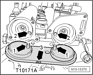
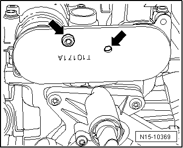
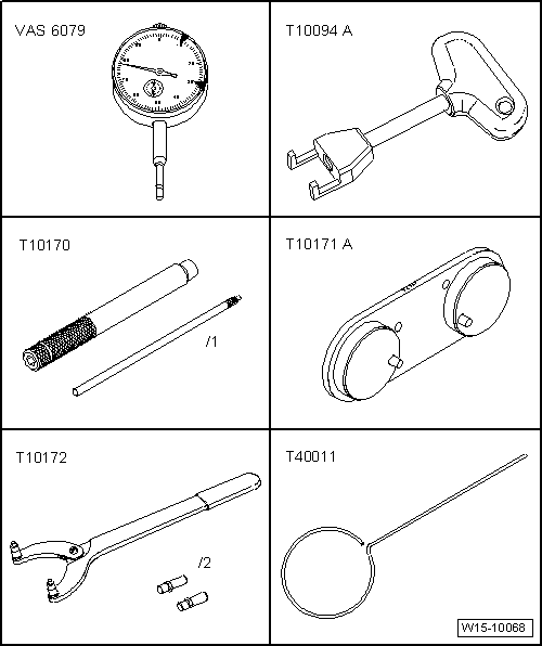
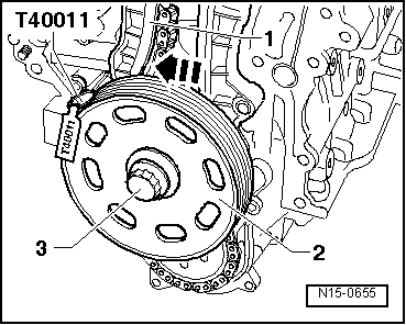
–  Screw an M6 bolt hand-tight into corresponding bore -arrows- (but do not tighten) to secure camshaft clamp -T10171 A-.
  Note
Note that there are different securing points for the camshaft clamp -T10171 A-.
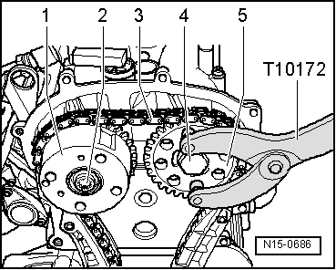
–  Remove camshaft sprocket bolts. It is absolutely necessary to use counterhold -T10172- for this.
  Note
The camshaft clamp -T10171 A- must not be used as a counterhold.
–  Remove one camshaft sprocket.
–  Place timing chain over camshaft sprockets, observing chain direction of rotation, and install camshaft sprocket again.
–  Tighten camshaft bolts until camshaft sprockets can still just be turned on camshafts.
–  Tension timing chain by removing locking pin -T40011-.
  N15-10369
–  Turn crankshaft in engine direction of rotation to TDC for No. 1 cylinder. Permissible deviation from TDC for No. 1 cylinder: ± 0.01 mm.
  Note
If crankshaft is turned more than 0.01 mm past TDC, then turn crankshaft back 45° against engine direction of rotation. Then turn crankshaft in direction of engine rotation to TDC for No. 1 cylinder.
  N15-0653
–  Release and pull off connector -1-.
–  Remove bolt -3- and detach continued coolant circulation pump -V50-.
  N19-10246
–  Unscrew plug -arrow- from crankcase.
–  Screw locking pin -T10340- to stop into crankcase.
–  Tighten locking pin -T10340- to 30 Nm.
  N15-10223
Locking pin -T10340- locks crankshaft in direction of engine rotation.
  N15-10227
–  Hold camshaft sprockets -1- and -5- in this position with counterhold -T10172- then tighten bolt -2- (left-hand thread) to 40 Nm and bolt -4- to 50 Nm.
  Note
Crankshaft must not move and timing chain -3- must remain tensioned on both sides when tightening camshaft bolts.
–  Remove camshaft clamp -T10171 A-.
  N15-0686
–  Unscrew locking pin -T10340- from crankcase.
–  Turn crankshaft 2 turns in engine direction of rotation to TDC for No. 1 cylinder. Permissible deviation from TDC for No. 1 cylinder: ± 0.01 mm.
  Caution
Before using camshaft clamp -T10171 A- you must check that the pins on the tool project by at least 7 mm.
If this is not the case, the camshaft clamp is defective and must be renewed.
The camshaft clamp must not be positioned using any kind of hammer.
  N15-10227
–  Insert camshaft clamp -T10171 A- to stop in camshaft openings.
If camshaft clamp -T10171 A- cannot be fitted:
–  Repeat adjustment.
If camshaft clamp -T10171 A- can be fitted:
  N15-10370
–  Screw locking pin -T10340- to stop into crankcase.
–  Tighten locking pin -T10340- to 30 Nm.
  N15-10227
–  Remove camshaft clamp -T10171 A-, hold camshaft sprockets with counterhold -T10172- and tighten bolts -2- (left-hand thread) and -4- a 1/4 turn (90°) further with a rigid wrench.
  Note
Camshaft adjuster centre bolt -2- has a left-hand thread.
  Note
Camshaft sprockets must not move on camshaft whilst tightening.
Further assembly is basically the reverse of the dismantling sequence. In the process, note the following:
  Note
The locking pin -T10340- remains in the crankcase until the crankshaft pulley is installed.
t  Install control housing → Chapter.
t  Installing crankshaft pulley → Chapter.
t  Install poly V-belt → Chapter.
t  Renew oil seals for camshaft sealing cover and oil them before fitting.
t  Specified torque for continued coolant circulation pump -V50-: 10 Nm
t  Specified torque for oil pressure switch -F1-: 25 Nm.
t  Fill coolant system with coolant → Chapter.
  N15-0686

Removing and installing timing chain and chain drive for oil pump > < Checking valve timing