volkswagen Workshop Repair Guides

Volkswagen Workshop Service and Repair Manuals

Adjusting valve timing > < Assembly overview
Checking valve timing
   
Checking valve timing
Special tools and workshop equipment required
t  Spark plug socket and extension -3122 B-
t  Torque wrench (5…50 Nm) -V.A.G 1331-
t  Dial gauge -VAS 6079-
t  Puller -T10094 A-
t  Dial gauge adapter -T10170- or dial gauge adapter -T10170 A-
t  Camshaft clamp -T10171 A-

  Note
The mounting points for securing the camshaft clamp were modified. A new special tool designated camshaft clamp -T10171 A- has been introduced. Previous camshaft clamp -T10171- can continue to be used if modified as described below.
   
–  Place template -1- onto camshaft clamp -T10171- as shown.
–  Mark camshaft clamp -T10171- at mark -2- using a centre punch.
–  Drill through camshaft clamp -T10171- using a 7 mm bit.
–  Deburr hole on both sides.
–  Additionally mark tool designation -T10171- with an »A«.
Test procedure
–  Drain coolant → Chapter.
  N15-10368
–  Remove securing bolts -1- from engine cover panel.
–  Detach coolant hoses -2- at engine cover panel and pull engine cover panel upwards.
  N15-10372
–  Pull coolant hoses off coolant pipe -1- and unscrew coolant pipe from camshaft housing and from cylinder block from below.
  N15-10373
–  Release and pull off connector -2-.
–  Remove oil pressure switch -F1--1-.
–  Remove spark plug from No. 1 cylinder. Use puller -T10094 A- and spark plug socket and extension 3122 B → Chapter.
  N15-10696
–  Screw dial gauge adapter -T10170- into spark plug hole to stop.
–  Screw dial gauge -VAS 6079- and extension -T10170/1- in to stop and lock in position with lock nut -arrow-.
–  Turn crankshaft in direction of engine rotation, to TDC for No. 1 cylinder. Note position of small needle on dial gauge.
  N15-10226
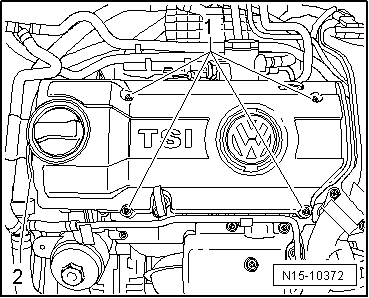
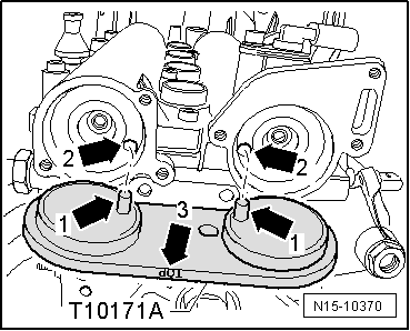
The holes -arrows- in the camshaft must align as shown. Otherwise turn crankshaft one rotation (360°) further.
  Note
t  
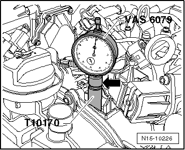
If crankshaft is turned more than 0.01 mm past TDC, then turn crankshaft back 45° against engine direction of rotation. Then turn crankshaft in direction of engine rotation to TDC for No. 1 cylinder.
t  Permissible deviation from TDC for No. 1 cylinder: ± 0.01 mm.
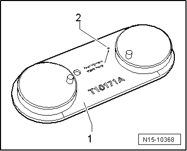
  Caution
Before using camshaft clamp -T10171 A- you must check that the pins on the tool project by at least 7 mm.
If this is not the case, the camshaft clamp is defective and must be renewed.
The camshaft clamp must not be positioned using any kind of hammer.
  N15-0657
–  Insert camshaft clamp -T10171- to stop in camshaft openings.
Locking pins -arrows 1- must engage in holes -arrows 2-. Inscription „TOP“-arrow 3- must be readable from above.
If camshaft clamp -T10171 A- cannot be fitted into camshaft openings to stop, then timing is incorrect and must be readjusted → Chapter.
Timing is OK if camshaft clamp -T10171 A- can be fitted into camshaft openings to stop.
Further assembly is basically the reverse of the dismantling sequence. In the process, note the following:
t  Renew oil seals for camshaft sealing cover and oil them before fitting.
t  Specified torque for oil pressure switch -F1-: 25 Nm.
–  Fill coolant system with coolant → Chapter.
  N15-10370

Adjusting valve timing > < Assembly overview