volkswagen Workshop Repair Guides

Volkswagen Workshop Service and Repair Manuals

Vacuum hose connection diagram > < Servicing air conditioning and heating - engine compartment
Heating, air conditioner
Air conditioner with manual controls
Installing and adjusting cables
 
N87-0050

Notes:

  • ◆ First connect cables to removed controls then adjust and secure cables to levers on air conditioner.
  • ◆ Sleeve ends of cables which are marked with a coloured line are attached to the controls.
  • ◆ Position cable sleeves -2- and -3- at stops on the controls and then secure. Secure sleeve for cable -1- =>Fig. 4 .
  • ◆ Adjust cables at flap levers with the controls installed.
  • ◆ All flaps must audibly contact stop when controls are turned.
 
N87-0050
  • Footwell/defrost flap cable
    • ◆ From air distribution rotary control knob to footwell/defrost flap
    • ◆ Black sleeve
    • ◆ Adjusting cable at footwell/defrost flap => Fig.1
  • Cable for central flap
    • ◆ From air distribution rotary control knob to centre flap
    • ◆ Black sleeve
    • ◆ Adjusting cable at central flap => Fig.2
  • Temperature control flap cable
    • ◆ From temperature rotary control knob to temperature control flap
    • ◆ Blue sleeve
    • ◆ Adjusting cable at temperature control flap => Fig.3
 
V80-0441

→ Fig.1     Adjusting cable at footwell/defrost flap

  • ‒ Install warm and fresh air controls.
  • ‒ Turn air distribution rotary control knob to stop at "defrost" position.
  • ‒ Press footwell/defrost flap lever onto stop -arrow- and secure black cable sleeve.
 
V80-0413

→ Fig.2     Adjusting cable at central flap

  • ‒ Install warm and fresh air blower controls.
  • ‒ Turn air distribution rotary control knob onto stop at "defrost" position.
  • ‒ Press central flap lever onto stop -arrow- and secure black sleeve.
 
V80-0412

→ Fig.3     Adjusting cable at temperature flap

  • ‒ Install warm and fresh air blower controls.
  • ‒ Turn temperature rotary control knob to stop at "cold" position.
  • ‒ Press temperature flap lever onto stop -arrow- and secure blue cable sleeve.
 
V80-0458

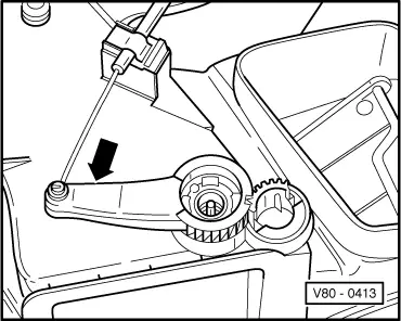
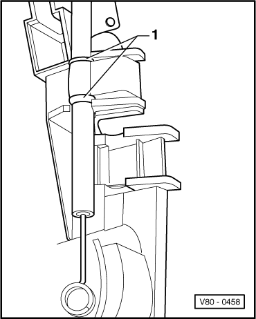
→ Fig.4     Securing footwell/defrost flap cable to control

  • ‒ Secure cable sleeve at blue marking -1- on control.
  • ‒ Secure inner cable to upper lever.
  • ‒ Adjusting cable on footwell/defrost flap => Fig.1

Vacuum hose connection diagram > < Servicing air conditioning and heating - engine compartment