
Passat (B3)
 |
|
 |
|
|
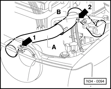
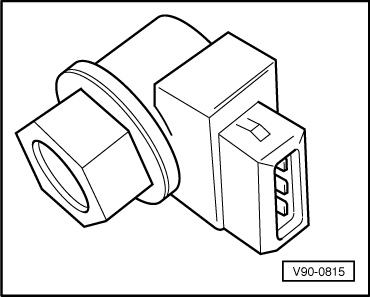
On vehicles with electronic speedometer:
|
 |
|
|
 |
|
|
 |
|
Note: Do not depress clutch pedal. On vehicles with mechanical speedometer:
|
 |
|
|
 |
|
|
 |
|
|
 |
|
|
 |
|
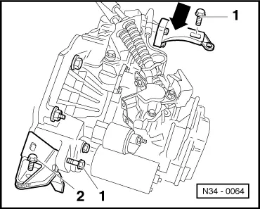
=> Repair group 27; Removing and installing starter.
|
 |
|
=> Repair group 26; Removing and installing parts of exhaust system, four wheel drive.
|
 |
|
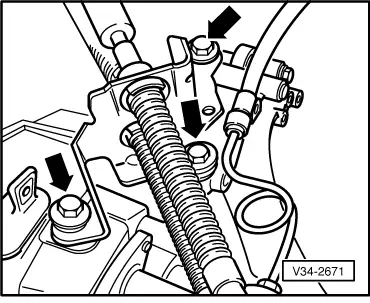
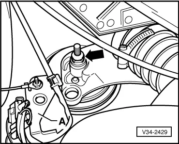
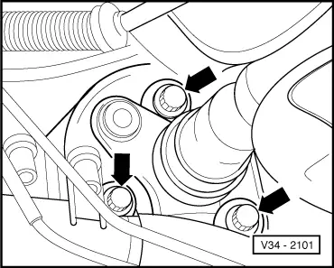
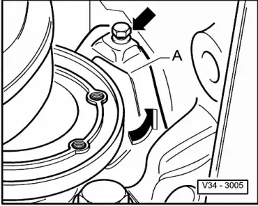
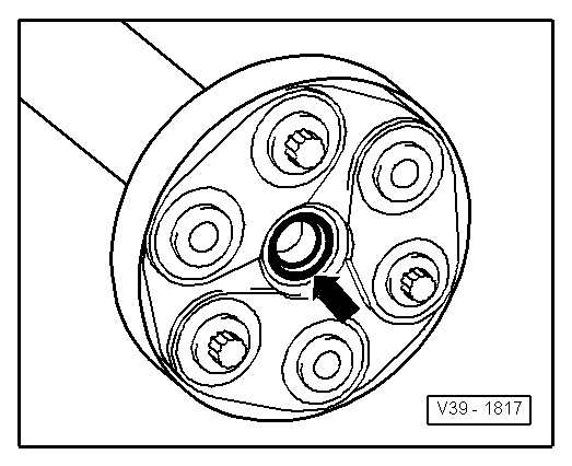
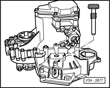
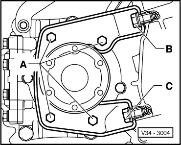
Note: When removing and installing the gearbox do not damage the seal in the propshaft flange.
|
 |
|
Note: Do not damage P.A.S. pipe when moving engine/gearbox assembly. |
 |
|
|
 |
|
|
 |
|
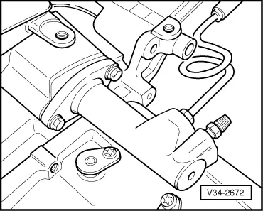
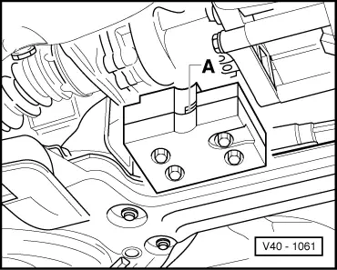
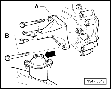
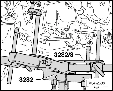
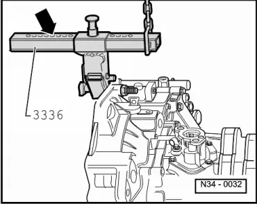
Removal position: |
 |
|
Note: → When removing and installing the bevel box do not damage the seal (arrow) in the propshaft flange.
|
 |
|
|
 |
|
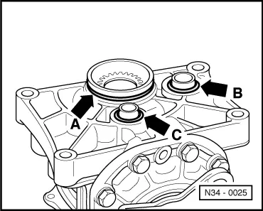
Notes:
|
 |
|
|
 |
|
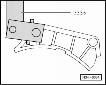
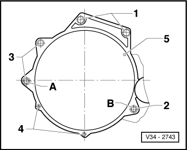
No. of holes visible = 5 |
 |
|
|
Installing Installing gearbox is carried out in the reverse sequence. When installing gearbox ensure engine/gearbox mountings are installed stress-free. => Repair group 10; removing and installing engine. Notes:
|
 |
|
|
 |
|
|
 |
|
=> Running gear; Repair group 40; Servicing drive shaft
=> Repair group 26; Removing and installing parts of exhaust system, four wheel drive
=> Repair group 27; Removing and installing starter.
|
 |
||||||||||||||||||||||
|
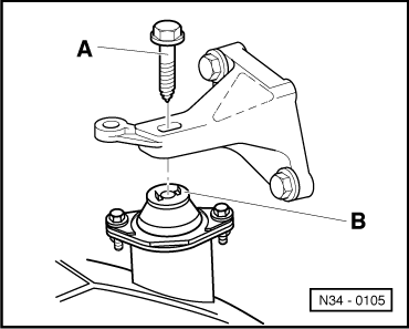
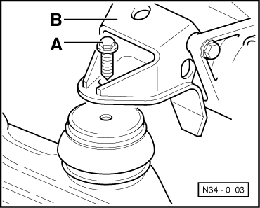
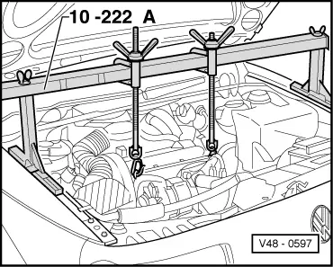
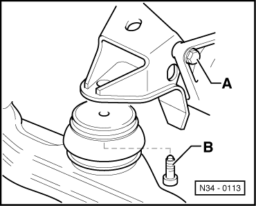
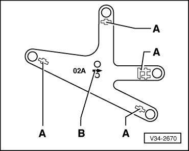
→ Assembly mountings
| ||||||||||||||||||||||
|
||||||||||||||||||||||||||||||||||||||||||
| ||||||||||||||||||||||||||||||||||||||||||