volkswagen Workshop Repair Guides

Volkswagen Workshop Service and Repair Manuals

Checking sender for throttle valve positioner > < Checking throttle valve positioner
Mono-Motronic Injection and Ignition system
Mono-Motronic injection and ignition system
Checking and adjusting idling switch

Special tools, testers and auxiliary items

  • ◆ Fault reader V.A.G 1551 or vehicle system tester V.A.G 1552 with cable V.A.G 1551/3
  • ◆ Hand multimeter V.A.G 1526 or multimeter V.A.G 1715
  • ◆ Test box V.A.G 1598/18
  • ◆ Adapter set V.A.G 1594
  • ◆ Adapter 1655
  • ◆ Feeler gauge
  • ◆ Current flow diagram

Vehicles ▸09.94

(Vehicles 10.94 ▸, )

Checking and adjusting idling switch (F60) gap

Notes:

  • ◆ The adjustment is only necessary if the throttle valve positioner or the lower part of the injection unit is replaced.
  • ◆ The idling switch gap can only be checked and adjusted when the plunger is fully pulled in.
    Use adapter V.A.G 1655 to pull plunger in. The adapter reduces the battery voltage by approx. 6V.
 
V24-0921
  • ● Ignition switched off.
  • ‒ → Pull plug -1- off throttle valve positioner -2-.
  • ‒ Connect adapter V.A.G 1655 to throttle valve positioner -2- and battery positive (+).
  • ‒ Hold plug -3- of adapter to earth (-) until the plunger -4- is fully pulled in -arrow-.

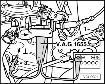
Note:

The injection unit is not connected to vehicle earth.

 
V24-0922
  • ‒ → Push plunger -1- by hand onto stop in direction of throttle valve positioner, check gap -a- with a feeler gauge and if necessary adjust with the adjustment screw -3-.
         Test specification: 0.40...0.70 mm
         Adjusting specification: 0.50 mm

Checking function

 
V24-0922
  • ‒ → Set hand multimeter V.A.G 1526 to measure resistance and connect to the lower contacts on throttle valve positioner -2- using aux. cables from V.A.G 1594.
         Specifications:
         Feeler gauge
         Not inserted ∞ ω
         Inserted: max. 200 ω

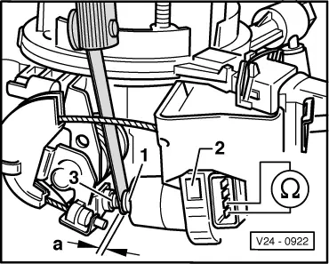
Vehicles 10.94▸

Throttle valve positioner (V60) with 6 pin connector

Notes:

  • ◆ The adjustment is only necessary if the throttle valve positioner or the injection unit lower part is replaced.
  • ◆ The idling switch (F60) can only be adjusted if the throttle valve positioner is fully out.
  • ‒ Connect fault reader V.A.G 1551 (V.A.G 1552) and select engine electronics control unit (address word 01); carry out selection with ignition switched on.
    => Page 01-3
 
→ Indicated on display:
Rapid data transfer     HELP
Select function XX
  • ‒ Input 04 for "Initiate basic setting" and confirm with Q.
 
→ Indicated on display:
Basic setting     HELP
Input display group number XX
  • ‒ Input 01 for "Display group number" and confirm with Q.
 
→ Indicated on display:
(1...4 = Display zones)
System in basic setting     1     ⇒
     1     2     3     4    

Checking function

  • ‒ Observe 2nd position from left in display zone 4 -8 digit number block-.
         Specification: 01000010
  • ‒ Open throttle valve slightly. The display at 2nd position from left must jump to 0
         Display: 00000010

If the specifications are not attained:

  • ‒ Carry out electrical check, test step 8
    => Page 01-19, if necessary renew throttle valve positioner (V60).

Checking adjustment

Note:

The adjustment of the idling switch must be performed in function "04 Basic setting" -positioner fully extended-. If the basic setting has to be exited for checking the wiring, the system must be brought back to basic setting with ignition switched on.

 
→ Indicated on display:
(1...4 = Display zones)
System in basic setting     1     ⇒
     1     2     3     4    
  • ‒ Select display group 00, to do this
    • ‒ On V.A.G 1551 press key 1
    • ‒ On V.A.G 1552 press key ↓
 
→ Indicated on display:
(1...10 = Display zones)
System in basic setting 0     ⇒
     1     2     3     4     5     6     7     8     9     10
  • ‒ Observe displayed figure in display zone 2 (throttle valve potentiometer path 1):
         Specification: 196...200
 
V24-1129

If the specification is not obtained:

  • ‒ Remove air cleaner or air intake elbow.
  • ‒ → Correct adjustment on the stop screw-arrow-.
         Setting value: 198±1
  • ‒ Press ⇒ button. The throttle valve positioner must move in to its start point.

Note:

If the position of the stop screw is corrected the function of the idling switch must then be checked .

  • ‒ Input 06 for "End output" and confirm with Q.

If it is not possible to adjust to specification:

  • ‒ Renew injection unit lower part.
<SOURCEMARKET> </SOURCEMARKET> <SOURCESYSTEM> </SOURCESYSTEM>

Checking sender for throttle valve positioner > < Checking throttle valve positioner