volkswagen Workshop Repair Guides

Volkswagen Workshop Service and Repair Manuals

Checking throttle valve control part > < Checking intake manifold change-over valve
Simos injection and ignition system
Checking air mass meter

Special tools, testers and auxiliary items

  • ◆ Fault reader V.A.G 1551 or vehicle system tester V.A.G 1552 with cable V.A.G 1551/3
  • ◆ Test box V.A.G 1598/18
  • ◆ Hand multimeter V.A.G 1526 or multimeter V.A.G 1715
  • ◆ Adapter set V.A.G 1594
  • ◆ Current flow diagram

Test conditions

  • ● Electrical consumers switched off (radiator fan must not run during the check)

Checking voltage supply

 
N24-0179
  • ‒ → Separate 3 pin connector to air mass meter.
  • ‒ Connect multimeter to measure voltage at connector contacts 2+3.
  • ‒ Switch on ignition
         Specification: min. 11 V
  • ‒ Switch off ignition.
  • ‒ Reconnect connector.

If no voltage is present:

  • ‒ Check wiring =>Page24-56

Test sequence

  • ‒ Connect fault reader V.A.G 1551 (V.A.G 1552) and select engine electronics control unit with the "Address word" 01. When doing this the engine must be running at idling speed.
    (Connecting fault reader and selecting engine electronics control unit .)
 
→ Indicated on display:
Rapid data transfer     HELP
Select function XX
  • ‒ Press keys 0 and 8 for the function "Read measured value block" and confirm entry with Q key.
 
→ Indicated on display:
Read measured value block     HELP
Input display group number XX
  • ‒ Press keys 0 and 1 for "Display group number 01" and confirm entry with Q key.
 
→ Indicated on display:
(1...4 = Display zones)
Read measured value block     1     ⇒
     1     2     3     4

Only continue with the test when

  • ● The coolant temperature is above 80 °C
    -Display zone 2-
  • ‒ Press C key.
  • ‒ Press keys 0 and 3 for "Display group number 03" and confirm entry with Q key.
 
→ Indicated on display:
(1...4 = Display zones)
Read measured value block 3     ⇒
     1     2     3     4
  • ‒ Check engine load signal in display zone 2:
         Specification ADY, AGG: 9.75...19.5 %
         Specification AFT: 12...17 %

If the specification is not obtained:

  • ‒ Check wiring =>Page24-56

Checking wiring

 
N24-0165
  • ‒ → Connect test box V.A.G 1598/18 to control unit wiring loom -arrow-.
 
N24-0179
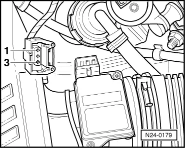
  • ‒ → Check wiring between test box and 3 pin connector for open circuit according to current flow diagram.
         Contact 1+socket 14
         Contact 2+socket 26
         Wire resistance: Max. 1.5 ω
  • ‒ Check wiring at 3 pin connector for short to one another according to current flow diagram.
         Contact 3+socket 26
         Contact 3+socket 14
         Contact 2+socket 14
         Specification: ∞ω

If no wiring fault is detected:

  • ‒ Check wiring from contact 3 to current supply relay (J363).
  • ‒ Check current supply relay (J363).

=> Current flow diagrams, Electrical fault finding and Fitting locations binder

If no wiring fault is detected and current supply relay is OK:

  • ‒ Renew air mass meter (G70).
<SOURCEMARKET> </SOURCEMARKET> <SOURCESYSTEM> </SOURCESYSTEM>

Checking throttle valve control part > < Checking intake manifold change-over valve